


Introduction
First we'll start with some typical repeater/link situations used in "two-way" radio communications. Ever listen to a conventional repeater setup, especially linked? The audio usually comes out rather tinny. If you ran a frequency response curve on the system the graph line would be like a camel's hump! To have a good sounding system repeat levels need to be well managed. When linking several stations together it's important to keep each repeater station's audio 1:1, flat and low distortion, otherwise, the problems will be additive on each hop to make up a poor sounding system. This is usually a problem with conventional phase modulated equipment. A passive system has the lowest distortion, however, has the drawback of not limiting a poor user over-deviating the system. Almost any radio can be modified to overcome these and other annoying conditions. With a carefully flat system setup the signals will sound like simplex. This document is a good place to start.
Acronyms, Definitions, Radio System Operation and Theory:
The very basics..........
Amateur Radio is to develop the art of radio and improving operating practices. This can set a good example for others, including the commercial industry, to what Amateur Radio system(s) are capable of doing to provide public service communications in time of need. This includes the technical side, to produce good operating repeater systems. We will start with very basic theory. Two-way radio systems send intelligence (voice, data, etc.) by modulating the originating transmitter and decoding (detecting) this modulation at the far end receiver back to something usable to be understood. How well this is understood depends greatly on how well the system is set up. Anyone can make a system work, "throw" it together and it will work, somewhat. This discussion promotes a better way. For one, technician organization and discipline is necessary. Plan on what you want to do for a system design and stick to it. Force yourself to keep good practices. One method to keep the guesswork out of working on a system is to establish level references. Some call these "benchmarks", or "baselines".
Most 2-way systems use the AUDIO (AF/VF) portion to modulate them. A typical (commercial) system uses 300Hz~3KHz for modulation and detection for a voice "channel". For this discussion, frequency modulation and level is somewhat different. While old Amateur methods used linear (volts, watts, etc) units of measure, most figures here mentioned are in logarithmic units. Once accustomed, it's easier to see the entire picture this way, when designing a system, checking frequency response, or even doing path analysis and keeps the guesswork out of trouble shooting a subtle level problem.
References can be expressed in a few acronyms. Test Tone level (TTL) into a two-way VHF/UHF transmitter or out of a VHF/UHF receiver is referenced to a test tone frequency of 1 KHz, of %100 system modulation. For this standard, that is +,- 5 KHz deviation. Other areas and services have different bandwidths, such as in P-25 systems. A Test Level Point, (TLP) refers to a measurement point, on equipment, for a system, in reference to Test Tone Level (TTL). TLP provides easy reference to any parts of the system for measurement and alignment. 0 dbm is referenced to 1 milliwatt at 600 ohm impedance. Therefore, a transmitter AF input with a TLP of 0 dbm, with a Test Tone Level of 0 dbm tone input, would fully modulate the system. A far end receiver with the same TLP would output a 0 dbm tone as well. A 6 db drop in (voltage) level would reduce the modulation in half, and so on. In general, for these standards, levels are stated in transmit-receive (Tx-Rx) order. Therefore, an audio (VF) "drop" TLP of 0/0 would mean a Tx TLP of 0dbm, Rx TLP of 0dbm. Sometimes operating levels are not at TLP. To avoid technician confusion two sets of numbers are sometimes used in diagrams and on the physical equipment. Figures in parenthesis are the TLPs. Non-parenthesis figures are operating levels, and, as mentioned, may be at a different levels from the TLPs.
System Design considerations
Long haul RF links are made of several transmitted and received signals. Each time this occurs some reduction in signal quality happens. Stock two-way radios are designed for single path operation, with it's own pre-emphasis, deviation limiting (clipping) and receiver de-emphasis. For multiple links, these stock radios can add gross problems, such as excessive distortion, audio frequency response being very poor. These conditions will cause a system to operate very badly and be rather annoying and fatiguing to listen to. These conditions can be corrected, such as used in the Mitrek repeater conversion project. The examples for this discussion are based on this and similar model of radios. .
For the transmitter condition, the mic input is not used, rather, the (flat) DPL (channel element) input is used. Each time you limit deviation for each hop will add more distortion. To correct this condition, only limit the modulation at one point, such as the system's controller. This is why the links should not be limited, rather passively 1:1. If you do have to limit, one option would be to set the system limit at 6 KHz and let the system user's transmitters limit at 5 KHz deviation. Passive mode requires system management and user responsibility. This may require some enforcement on the user's part. There are other circuits to "punish" or "correct" over modulated users which is beyond the scope of this documentation.
For the receiver's audio frequency response condition, take each receiver audio off the discriminator. All receiver's discriminators should have great low end response, however, (due to IF filtering restraints) the top end normally rolls off too soon. There is an audio board with circuitry to equalize the higher end to extend the response.
Emphasis in originating audio and de-emphasis in destination audio is similar to "Dolby" used in audio tape systems, which increases the highs during recording and decreases the highs during playback. There's more in "Dolby" such as 'companding' the highs but for this discussion the result is the same as in two-way radio: it improves the signal to noise ratio of the received signal.
Conventional audio
Most FM equipment uses a 6 db per octave pre-emphasis in the transmitter audio. The opposite happens at the receiver called de-emphasis. If the exact pre & de-emphasis was made at each hop with low distortion there wouldn't be much of a problem. Unfortunately, this is not the case with conventional equipment. In some cases you may be"forced" into staying with a conventional system. Some examples; would be interfacing with another repeater group that does not recognize flat audio (for various reasons, such as lack of understanding or attitude/management issues, etc.) Another example is "VoIP" linking, such as use in IRLP. Another example would be for lower speed Packet nodes. To address these situations Author did some research and development for circuits and the values, for the Mitrek radio, to assist you in your project building. Using the (mentioned) audio board for a base amplifier platform you can modify the circuit and change some component values. Or you can build separate circuits for the transmitter and receiver of a link/repeater, as shown on the pictures. On the left is a simple de-emphasis circuit. It was fairly easy to obtain 6 db per octave roll-off for the receiver. For the transmitter that was more difficult, therefore, only a dual stage for pre-emphasis is recommended. The values shown here are for the two (good) circuits, which should work for the Mitrek radio with a specification well within 1/2 db from 300-2400 Hz voice band. The top end (3000 Hz) should be close enough not to cause any problem to most interfacing with conventional systems. For other equipment you may have to experiment with the proper values and perform a frequency sweep. The point to bear is there are alternatives to dealing with the interface between conventional and flat systems.
Flat audio
The best way to link with another system (and club) is to "spec" a system for flat audio. This works if there are no political issues meaning, people problems.
The idea is nothing gained or lost within the system, while the users provide the proper signal to noise management. The originating signal is pre-emphasized in the user's transmitter and is de-emphasized in the user's receiver at the other end of the link. Sub-audible signaling now can be utilized, since each hop's low end frequency response is extended to 40 Hz or lower. The results are the same as working simplex: natural, unprocessed, clean audio both ways. Therefore, remove or bypass all pre and de emphasis, from the transmitter to the receiver, for every link. The stock P.M. is used only for the local mic, for service work, or auxiliary tones, beeper, ID'er, etc. With repeater equipment, the F.M. section is added for the repeat audio. When doing this certain precautions should be observed. For the modulator needs to be checked (and adjusted) for deviation linearity and temperature compensation. The receiver needs to be swepped and if necessary, equalized for the mid and top end.
The other complication is human understanding, terms and attitudes. Flat audio can be specked for any scale. For example, a standard voice channel of 300Hz ~ 3KHz may be considered "flat" if no peaks or dips are observed during an audio frequency sweep. PM equipment can do this however, most stock equipment does not; hence, the experience of non-flat audio. Other standards can be realized. For example, the Author specs flat audio for 20Hz ~ 5KHz, which, of course would sound much better than the previously mentioned "voice channel" or "conventional audio". One has to look at the big picture to realize that it's not the method of audio circuits but in fact the results of the signal.
The last consideration is external circuit arraignments. For example, if a user's radio is talking to a flat repeater station his/she audio being prempasized is not compatible with external circuits such as the PSTN during a phone patch. The reverse signal direction (line to repeater/station) will need to be emphasized to be compatible with the user's deempasized receiver audio (response curve). For LMR most radios utilize a 6 db per octave on the transmit and receive audio response curves. Last complication is some Chinese radios have a (hidden option sometimes) the pre and de can be switched on or off. This can lead to further misunderstanding and poor audio experience.
Extensive research and development was invested since 1985, in this area by the Author with limited resources. These modifications are not perfect, however, should work for your project. There are several systems working well in service, including SRG's and two other club's in the area, so these ideas and circuits should work for you. You should HAVE the knowledge of F.M. principles including how a FM receiver discriminator works. You might read up on repeater operation principles, too. Information is available in radio books, such as the A.R.R.L. Radio Amateurs Handbook.
Audio alignment for your radio
This is an area with some misunderstandings, apparent from bad sounding stations on the air, specifically on 2 meters. This is reinforced by many folks getting used to these kinds of signals, therefore "adapt" and consider this to be "normal". Far from it-the truth is FM stations can sound great in simplex or on a repeater. This is assuming the latter is set up properly, as covered earlier. Typically, someone will get on a repeater and ask for a "radio check". This term is not only misleading is a reflection on the experience of the operator. It's tempting to say as a reply "how much did you want the check made out for?". Seriously, one should ask for a "signal report" or just simply ask "how's my signal?".
To achieve a good sounding station the owner/operator needs to properly set up the radio's transmit audio. Many modern mobile radios are use for both mobile and base station. They typically come from the factory with too much audio sensitivity. The mobile (high noise environment) is the last place you want a sensitive microphone. To make matters worse some of the old timers still use old (tube-AM) school of having to get to close to the mic. The two factors make a bad, distorted signal. A third resultant of being too close to the microphone is the "phiss" "popp" sounds from the wind on the users lips. This is not only annoying to listen to it adds further to the problem of poor transmitted audio. These folks may not be aware of this problem. Sometimes this goes without comment or correction contributing to other problems such as lack of quality people responses or contacts. A person hearing a bad signal may be reluctant (or ignorant) to the problem and want to keep the contact short and move on. To become part of the solution one first needs to communicate, ask, investigate and make corrections.
Microphone gain and deviation limiting are many times misunderstood. The Author is here to educate the ignorant. The two adjustments (if any) are inside the radio on the PCB in the form of physical potentiometers. Some late radios have "soft pots" where is, a software menu selection makes the audio changes. For the Northwest of U.S. just about all simplex and repeater operation calls for +- 5 KHz operation. For the simplest description the term "channel" is used to stress the operator to use the standard frequency slots suggested by the A.R.R.L. for the band-plan. By keeping your transmitter to deviation limits and using the proper frequency slots (channels) interference can be minimized or non-existent. This is a good thing.
Always set the deviation for the maximum setting of 5 KHz deviation. Next, adjust the mic gain for a voice average of 3-4 KHz deviation. This will partially depend on the environment the radio is used and the operator's voice. For example, operation in a noisy truck the sensitivity will be 5-10 db lower than in a passenger car or base station. A scope (on a service monitor) is the best way to display, observe and perform these adjustments. If the mic gain is too low it will be hard to be hear. If it's too high it will make distortion and possibly "cutting out" on a repeater and be irritating for others to listen to.
Another complication is the newer radios have a (lame) design to combat background noise by manufacturing a microphone with a very small orifice (hole) for passage of sound to the microphone element. When taking real close to this type of mic makes strong sound wave to the element. If the operator "drifts" off/ moves the distance from one's mouth the audio drops off sharply. This make inconsistent audio level, even more hard to understand from other stations. This small hole can also (in some cases) product sharp, tinny audio, making it irritating to listen to as well. The older radios had a much large surface area for capturing audio, thus, the voice levels were more consistent and better sounding. An audio compressor is not a solution; it just brings up the background noise. It also makes the voice unnatural. As mentioned earlier many folks get used to this type of compression, thinking this is again, "normal". One solution for the modern (small holed mics) is to enlarge this hole, then turn down the mic gain a little. Good operator practice is to address these issues.
The Author set up a measuring device for mic gain. This is a enclosed (small) speaker with the appropriate cable and connector to feed it. In this case a set of banana plugs to fit most any bench connection. The speaker is driven with a 1 KHz (test type) tone, with an AC voltmeter across it, (in bridge mode) calibrated logarithmically thus, in dbm. The mic is held against the speaker, while the tone is adjusted to produce 2/3 system modulation, AKA, 3.3 KHz deviation. Doing this keeps the radio out of limiting (clipping). The level of the tone is observed and adjusted to a standard for the environment. This is obtained from the earlier paragraph on setting the mic gain for voice average of 3-4 KHz. For this standard most radio's mic sensitivity will be between -10 and 0 dbm. Once the level is found to be satisfactory all the radios can be set up the same, thus taking the guess work out.
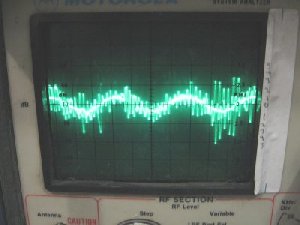
There are still radios out there with improper settings when it comes to the transmit audio. To illustrate this point a couple of local, regular users's signal signatures where monitored and recorded off the air with a calibrated service monitor. The signal from the repeater's output to the monitor was strong, full quieting as not to add path noise or other alterations from the signals being observed. Ric, KE7KKH and Dan, KE7BMZ were the two stations in this case.
Ric's modulation is the right amount of peaks; occasionally reaching the maximum. Note the CTCSS tone is too high; typical for most radios and normally not adjustable.
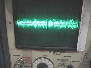
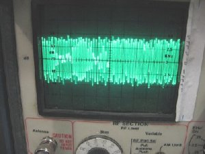
In the case of Dan's signal, the mike sensitivity is set way too high. The waveform on the left image is in between words; that's the background noise being transmitted. The right image revels the ugly truth; almost the entire content is fully modulated, causing a lot of distortion. This would be an annoying signal to listen to. This condition is correctable, in many cases, with a simple resistor (ranging from 1K to 100K) in series with the radio's transmit audio line.
Another word on compression; which is undesirable for analog FM. The equipment needs to modulate the transmitter in a linear, dynamic type of arraignment. Some hams have a radio with very heavy compression and get a good signal report as great "broadcast" quality. Most broadcast stations (AM, FM and TV) use a lot of compression therefore, those folks who watch and listen to this type of audio get "use" to it with a conditioned mindset that this is a normal voice. This is far from the truth in comparision to listening to someone in person. The other complication is the compressed station does not have to listen to such issue and/or develops an attitude not caring what kind of audio he/she sends out. This is few (thank goodness) but they are out there. This issue may be fixable with the knowledge and experience on setting up a radio properly.
Other notes
A word or two on operational amplifiers. The I.C. LM324 is a really slick, versatile I.C. (many hams call them a "chip" which is only slang). For cor buffers, and timers it's in the differential mode. You can get four timers in one chip, while the 555 is a single timer. The output will go to zero volts for logic low; perfect for TTL-CMOS interface. For the audio and filter stages it's a high gain, low noise and distortion device. Remember the dual power supplies, using the charge-pump, etc, with the LM741 ? Not anymore. The 324 runs on any single end supply from 5 to 15 volts, positive. Up to a 5M pot can be used for the negative feedback loop for high gain audio amps. For examples of application check out the other articles on the tech page.
![[SRG home Direction]](images/srghome.gif)