Back to SRG tech page
![[SRG home Direction]](images/srghome.gif)
Introduction and History
Now that you've probaly read the other article about modular plugs and various type of CAT cables, here's some disscussion on the RJ-11 (Telephone) standards. For this disscussion we will be using modular componants for both types of systems (RJ11 and network modular).
Panduit's one of a few brands that makes wall mount RJ-11 and network parts. The other two brands well known are Leviton and Allen Tel Products. The advantage of the first two brands is they are likely to be locally available at most telecommunication stories/distributors. The "RJ" meaning, Register Jack, is from the old Tel.Co. days. It's an acronym like the USOC, which is Universal Service Order Code. The (PDF) file from Panduit's web site is not very friendly into showing the "newbie" on this simple, but intemidating task. Therefore, this article may help you.
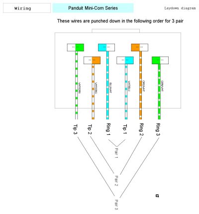
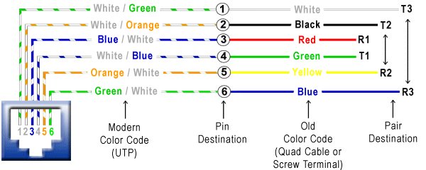
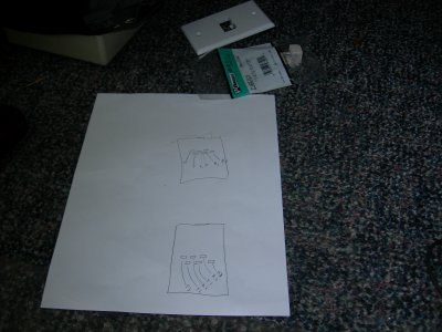
A handy diagram might be worth printing out to take with you. Choice of two versions. They show you the way telephone pairs work with eithernet/RJ type terminations, however, this is not eithernet wiring, only the same hardware of plugs and jacks.
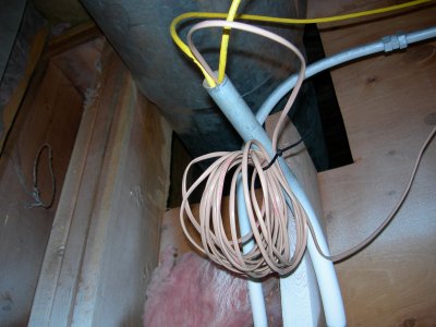
Now, to start with the project, first fish the tape up the conduit and hook the end of the cable to it. Since most fish tapes have that annoying "bump" at the end you might want to push that into the conduit before pulling. At the lower end pull out about 12" to play with.
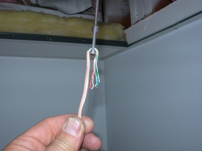
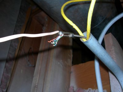
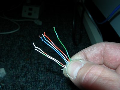
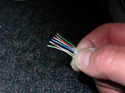
It's a good idea to leave the rest of the cable (don't cut to length) by "storing" it as a "service loop" inside the ceiling. Next, strip off the outer jacket and refer to your "cheat-sheet" for layout of the wire colors.
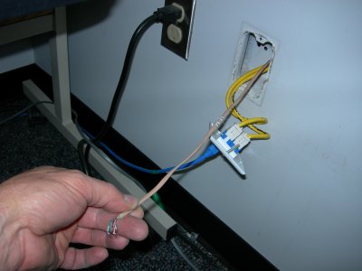
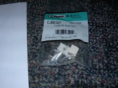
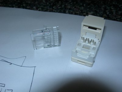
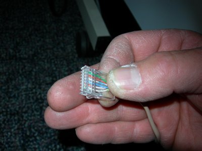
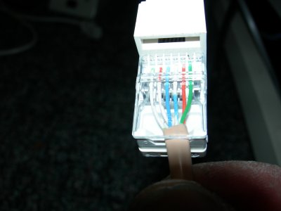
The Panduit package used for this demonstration is the # CJ66IWY. Be careful on the "IW" part, which means international white (whatever that means). So if you walls are white, better order the correct color plate and jack. For this installation, the IW was okay, since it would stand out a little from the (white) wall plate to see the actual jack edges. It's being shared with Ethernet (blue) RJ-45 jacks, so the IW helps ID the different service. In this case is an analog drop. Remove the two pieces and spread out the wires, to the correct order using your sheet.
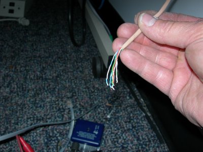
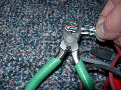
Cut any frayed ends off, keeping the correct order of colors. Remember, this is a RJ-11 project therefore, there's only three pairs you'll be working with. Then insert them into the cover/crimp part of the connector
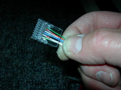
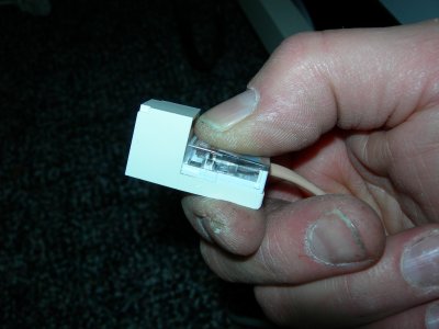
Push the wires up the point of the outer jack near the connector, as shown, then cut off the excess. The outage jacket sould be included in the crimp area, for best strenght.
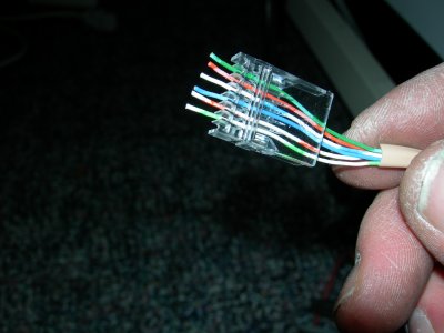

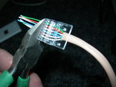
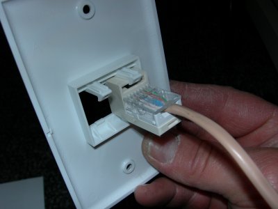
While holding the prepped top piece, push it over and onto the main connector part, pushing and/or squeezing down to the click/latch. It should snap into place. Here's what the termination should look like.
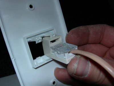
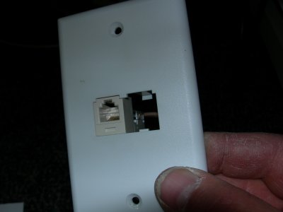
Now, insert the connector into the wall plate, starting with the bottom, hooking on the little tab of the plate. Then swing it up into place. Again, it should snap into place. Here's what the wall plate should look like; on both sides. Either plug the empty hole or install the second jack. The plate is now ready to screw into the (duplex) box inside the wall, for the finished product.
Back to SRG tech page