Introduction
Most all communication equipment generates heat. Heat normally comes from current flowing through wires, and semiconductors. The latter is the most area of "IR losses" AKA, heat loss, due to current flowing through them and the fact they are semi conductors. That means they have resistance. Resistance to current flow generates heat. The higher the voltage drop worsens the heat issue. In the case of RF transmitters that run medium to high-power presents large heat issues. A linear transmitter is the worse, however class "C" transmitters have their issues as well. The latter is normally used for LMR-FM systems. Since SRG's system is such, this discussion will focus on that.Engineering
For SRG, most of the link radios operate in the +40~43 dbm area, therefore, heat generation is moderate. The system output transmitters operate a few db higher, therefore, heat generation is more severe. Used are the Motorola Micor transmitters. For the micor is normally designed for +15 volts from the stock power supply. Running the transmitter at "rated" power out is just too hot for SRG's specs. One (slick) method to keep IR losses down is to run the final (major heat source) transistor's supply lower than factory spec. A special power supply with custom transformer windings is used. Documentation for this supply is elsewhere on this site. They output + 10 volts nominal. "Nominal" means that vary +- 10%.
Even with lower voltage approach during long transmissions the transmitter still gets too hot for "comfort". Therefore, a second measure is taken with a fan. Fans are very much used and depended on as a primary source of cooling for all kinds of equipment such as transmitters, computers, servers, etc. Most of industry designs these fans to run continuously. This can lead to shorten fan life, dust accumulation and annoying-distracting noisy environments.
Solution
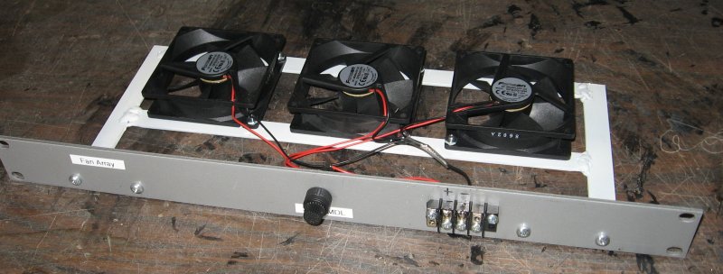
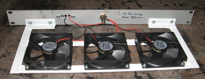
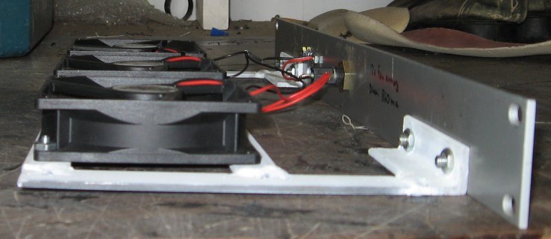
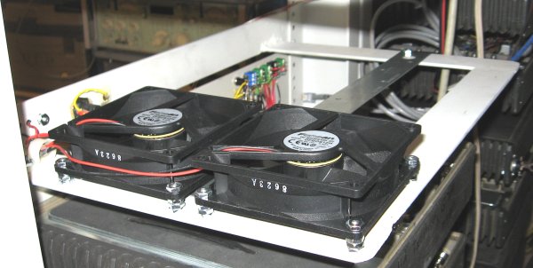
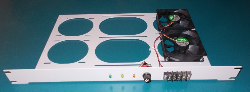
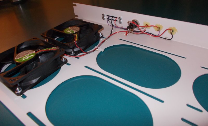
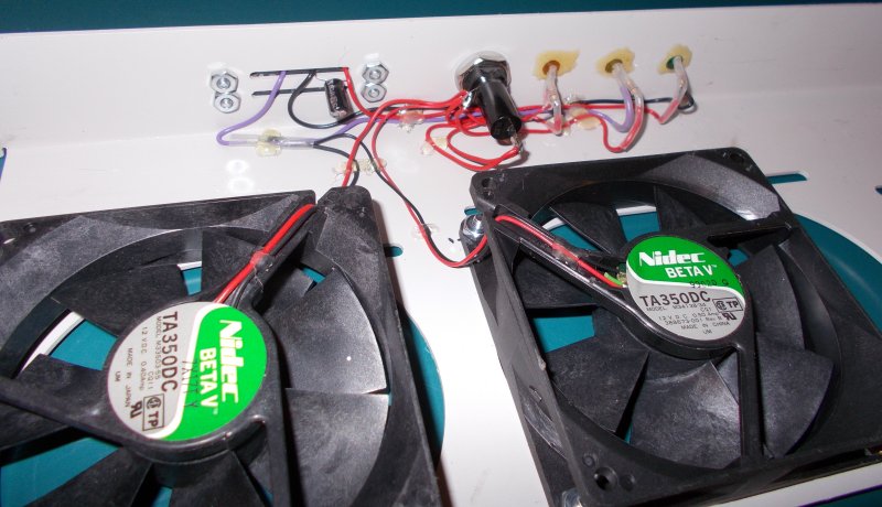
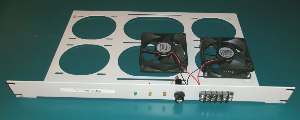
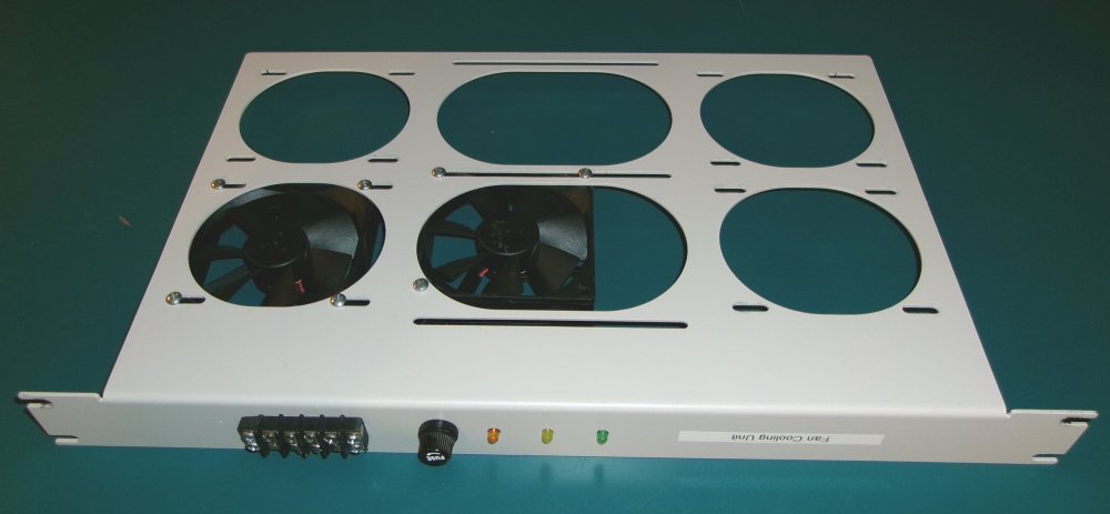
SRG's spec calls for a fan cooling, if necessary, but only when cooling is needed. Therefore, a FCU (Fan Cooling Unit) was designed. Several prototypes were built, along with a couple production units and put in service. Two or more fans are mounted in an assembly (in parallel) and only come on when the transmitter starts to get hot. This is done by a thermostat mounted on the head sink of the transmitter. Its normally open contacts close at 120° F. Power to the fan "assy" is switched by the thermostat. The minus (-) side is switched making it very easy to "test" the fans by touching this control line to ground. Also, insulation is not important on the minus side, being the equipment is negative ground. The fan assy only occupies one RU (rack unit). Power on the front; + runs to the fans, while the - runs to a remote switch, in the form of a thermostat in the appropriate spot.
Of course, this circuit should be fuse protected. For older versions the fuse is on a power supply's output buss-fuse array, located elsewhere. Later versions have a fuse holder right on the panel. Either use a panel mounted 3AGC holder Hosfelt Electronics part number 342014A or a surface mount single gang holder Mouser Electronics part number 534-3536. This give you a choice where to fuse the FCU.
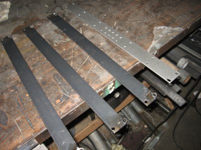
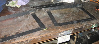
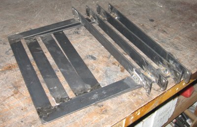
Three version were built:
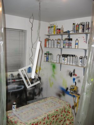
A visit to the "painting room".
For finish construction you'll need to increase the terminal block mounting screws with a 9/64" bit, and for the LEDs a 13/64 bit as well. Use four 6-32 x 1/2 P pan head screws with four 6-32 nuts to secure the terminal block. Glue the two LEDs in the new holes. The blinking yellow one towards the AG3 fuse holder and the green one in the other.
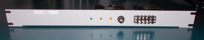
Newer version for 2012After careful planning and coming up with these prototypes a production version four of the FCU was done in the spring of 2012. The three indicators are kept in this version; Power, fan active and fuse fault.
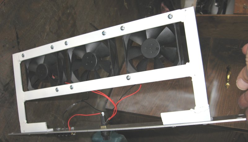
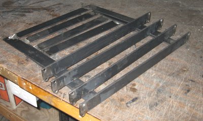
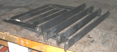
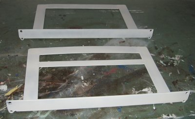
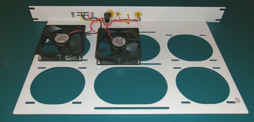
The mounting holes in each side are for 92 mm fans. The center ones are for something larger. This give you some options.
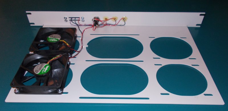
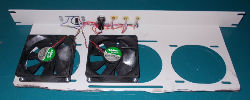
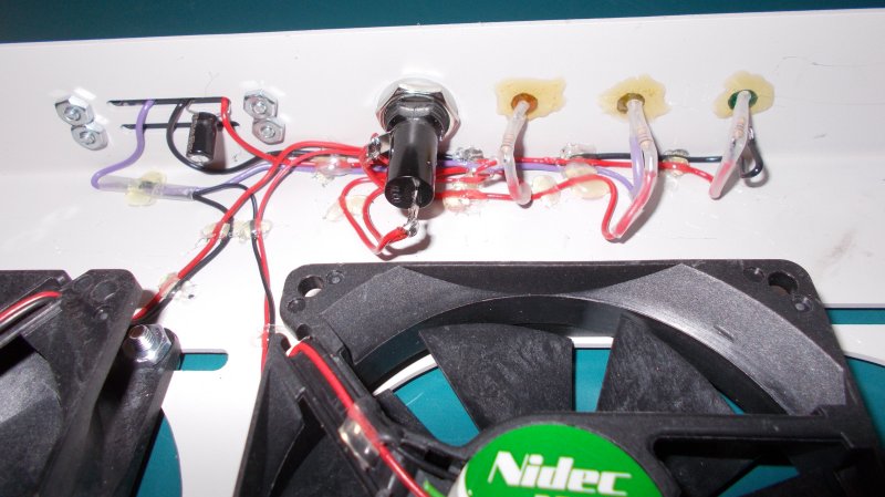
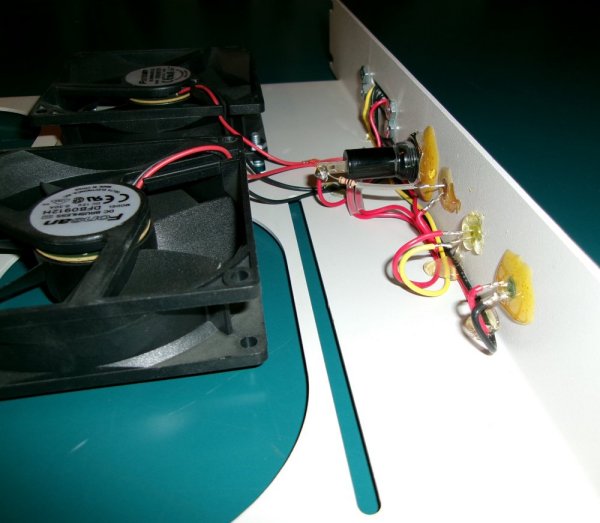
Using hot glue to dress some of the wires works pretty well.
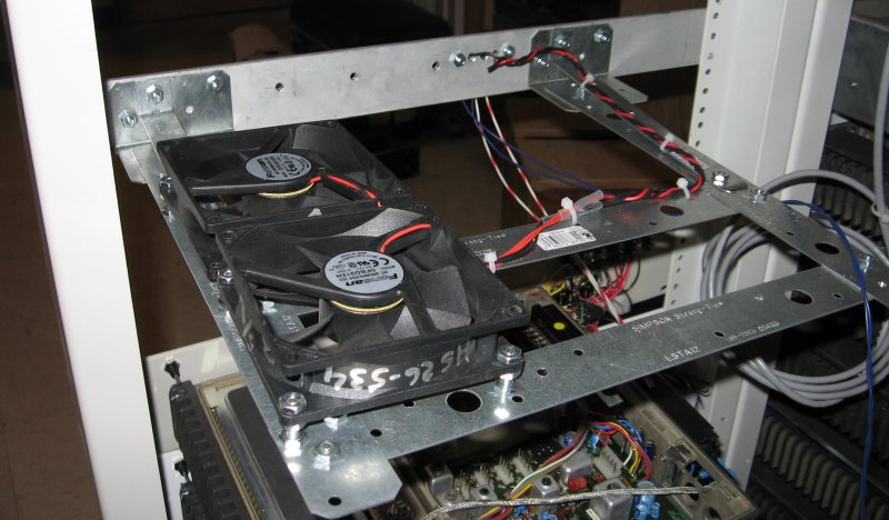
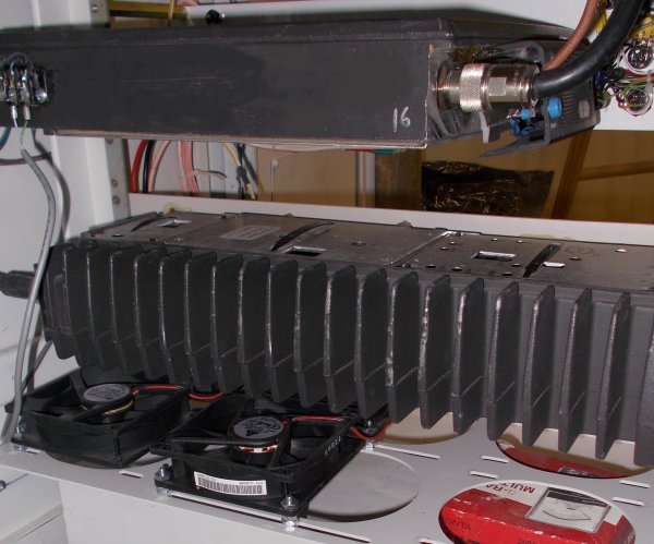
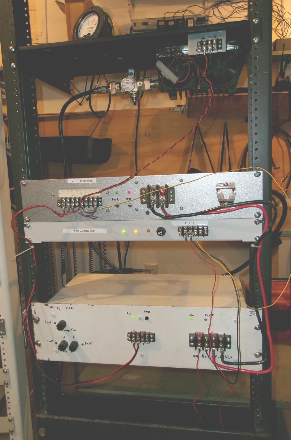
Shown here is one in service; the fan cools both radios.
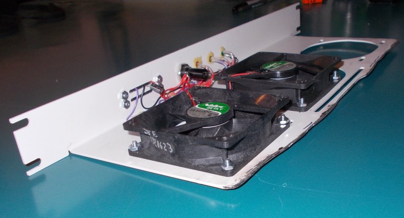
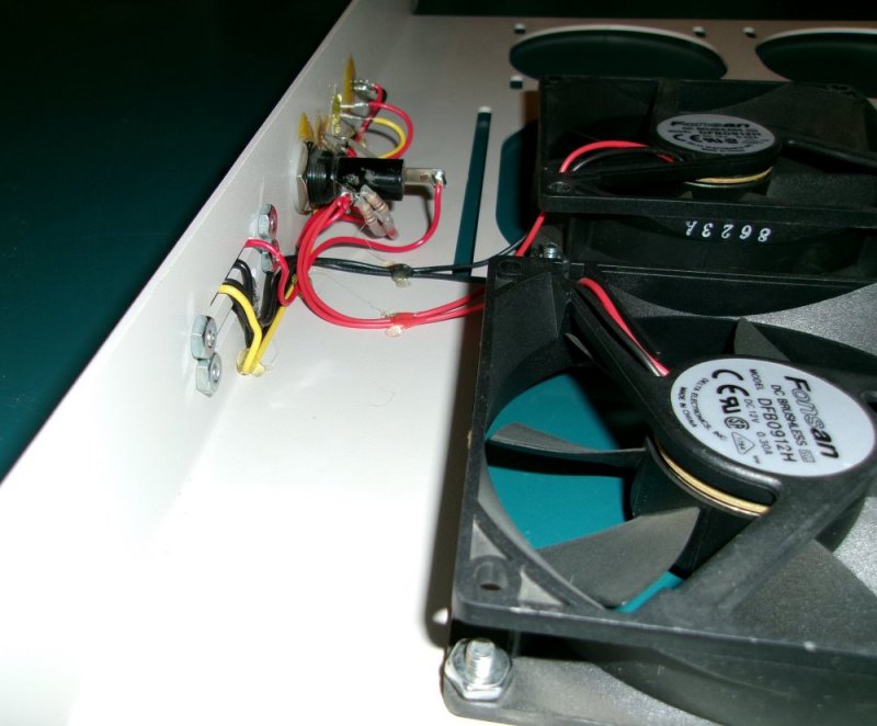
Here's a modified chassis specifically for the micor transmitter in a cabinet with limited space for the depth.
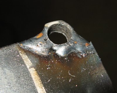
It's not pretty, but gets the job done.
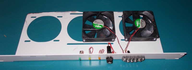
Lables were added after this picture was taken.
In 2023 version four was realized. This unit was used for testing a transmitter on a test rack.
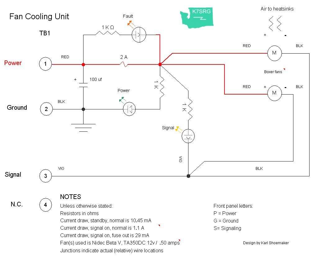
Here's the schematic drawing of this unit.
Back to SRG's tech page.
![[SRG home Direction]](images/srghome.gif)