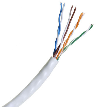
CAT 7: An informal name applied to ISO/IEC 11801 Class F cabling. This standard specifies four individually-shielded pairs (STP) inside an overall shield.
Designed for transmission at frequencies up to 600 MHz.
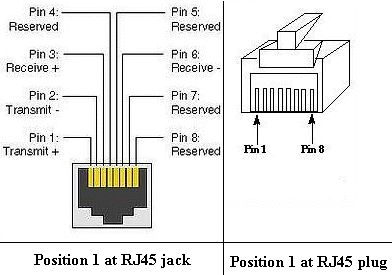
The "RJ-45" plug
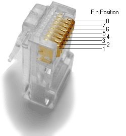
The "RJ-45" end is really a 8-position modular connector that looks like a large phone plug.
Many (incorrectly) call it the "RJ-45", but since the "J" stands for jack in the UOSC it's really a (male) plug.
However, for ease of understanding the whole system we'll use the (incorrect) term a few times in this document.
There are a couple variations available.
The primary variation you need to pay attention to is whether the connector is intended for braided or solid wire.
For braided/stranded wires, the connector has contacts that actually pierce the wire.
For solid wires, the connector has fingers which pierce the insulation and make contact with the wire by grasping it from both sides.
The connector is the weak point in an ethernet cable, choosing the wrong one will often cause grief later. If you just walk into a computer store,
it's nearly impossible to tell what type of connector it is.
10/100 ethernet cables have 8 wires, of which 4 are used for data in the form of two pairs, in a twisted pair setup: one pair for transmit and one for
receive.
The other wires are twisted around the data lines for electrical stability and resistance to electrical interference.
The cables end in RJ-45 connectors that resemble large telephone line connectors. It's important to be able to identify the pin number on these plugs.
During some research an interesting type was found on Platinum Tools web site.
Their connector lets you run the wires out front of it. In some cases this may help with flimsy wires, such as stranded. That may be another reason for
going with solid; easier installation.
Later on you'll be working with Switches, HUBs, Routers and NICs ("NIC" acronym means Network Interface Card). Some or all are used in a LAN
(Local Area Network).
NICs have a network jack and are plugged into the mother board of a PC (Personal Computer). That is how a PC communicates to another devices on a LAN, or even the
internet.
When you connect a bunch of machines together using a hub, the hub relays all the information from all the transmit pairs to all the receive pairs.
That is, each machine sees on its receive pairs the information sent on every machine's transmit pairs.
The hub logically connects all the transmit pairs to all the receive pairs.
Connections between 10/100 ethernet adapters are made using cables that run to an ethernet hub or switch.
Hubs electrically connect your computers together and switches act like traffic cops making your network more efficient.
All these devices can be studied and learned on other documentation. We are concentrating on the cables at this point.
Wiring Standards
Now, for one of the most confusing part for the "Newbie". There are three kinds of wiring schemes are used for commercially made ethernet cables, which
are:
Rollover For this article we will not be covering rollover.
T 568 Standards:
The TIA/EIA-568 specifies two wiring standards for a 8-position modular connector for network connections.
The two wiring standards, T568A and T568B vary only in the arrangement of the colored pairs.
The only difference is in the orange and green pairs, for wire colors.
You can use either standard, as the signals don't care what the colors are, just that you keep to the standard at each end.
Your choice might be determined by the need to match existing wiring, jacks or personal preference, but you should maintain consistency.
Sources suggest either way.
Just to give you another (confusing) decision, sources indicate that traditionally B is used because of the AT&T 258A standard, however,
The U.S. N.C.S. Federal Telecommunications recommendations do not recognize B.
US Government specifies A since it matches USOC cabling for pairs 1 & 2, which allows it to "work for 1/2 line phones...".
There's more on this point at the end of this page.
A straight through cable is used to connect DTE-to-DCE or DCE-to-DTE devices, like a hub or switch, or a NIC (in a PC) to a switch, because they are
unlike devices.
The wires are is just that; pin-for-pin on each end of the patch cable are the same colors, therefore, the transmit and receive wires are straight through.
You can identify a straight through cable by holding both plugs (ends of the cable) side-by-side, in the same orientation.
For example, hold both plugs with the locking clip pointing down and the cable pointing towards you.
The color of wires will be the same on each plug. If a cable does not say crossover, it is a probably a standard patch cable. More on this thought, later.
A cross over is used to connect DTE-to-DTE or DCE-to-DCE devices, like two NICs, (each inside two PCs) because they are like devices.
An ethernet crossover cable has it's send and receive wires crossed. This type of connection in a peer-to-peer fashion can be done without a hub/switch.
This is rather common in home networks.
Watch out !
Products sometime surprise you and cause confusion, so be ready.
For example, when using a hub or switch, this is automatically done for you, so in that case you would not use a cross over cable.
Some interfaces can cross and un-cross a cable automatically as needed, which can really quite nice, in a way, or cause confusion, when adding other devices to
the mix.
Examples would be cable and DSL modems that have their actual ethernet plugs/jacks (perhaps) reversed.
This is to allow people to hook up a cable modem to a computer without this (special) crossover cable.
TIP: If you run into trouble and your devices are not working, you might try a different cable standard in case the auto-crossover in some devices is "hosing"
you up.
Again, you can identify a cross over cable by holding both plugs (ends of the cable) side-by-side, in the same orientation.
In this case, the color of wires will not same on each plug, left to right.
You'll notice the green and orange pairs have been rolled, while the blue and brown pairs are straight as in the picture shows.
As mentioned earlier, a crossover cable is not to be confused with a "roll over" cable, which is not covered here.
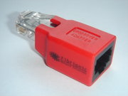
The other pictures shows the alternative by using a cross over adaptor, with a straight through cable.
Either way accomplishes the same task.
The Author uses way to remember which is by thinking that a crossover cable is the same as terminating one end with 568-A , while the other end with 568-B
standard.
When making up your own cables, the Author uses two other methods, which are to label them and/or use different color cables for each type.
The most popular crossover cables made are:
Crossover cable |
Sample application |
Ethernet crossover cables |
Ethernet card to ethernet card type |
RS-232 serial crossover cables |
PC to PC, PC to printer type |
V.35 crossover cable |
Router to Router type |
RS-449/RS-422, X.21 and RS-530 crossover cables |
DSU/CSU to DSU/CSU type |
T1/E1 crossover cable |
Switch to Switch, DSU to DSU, etc |
How to wire your own ethernet cables and connectors.
What You Need:
Required:
CAT 5 Cable - bulk Category 5, 5e or 6 cable
8P8C male ends
Crimper for them
Wire Cutters - to cut and strip the cable if necessary
There is also a pull string inside the group of wire pairs for the same reason.
Also Recommend:
Wire Stripper
Cable Tester
About the Cables and the Connectors for them:
Most professionals will advise you do not build your own cable, but rather to purchase factory made cables. It's an art to build a proper cable and connector.
This will keep another variable in a troubleshooting nightmare, in the event this should happen to you.
If you still choose to build your own you will need to know about cables, and the connectors for them.
You can find bulk supplies of the cable at many computer stores or most electrical or home centers.
You want UTP (Unshielded Twisted Pair) Category 5 cable for basic 10/100 functionality.
You should run CAT5e whenever possible because there is usually not a cost difference from CAT5 if you look hard enough.
Moreover, if you install higher rated cable, now it will give you a measure of future proofing.
Bulk cable comes in 2 basic categories, solid and braided cable.
Braided cable tends to work better in "patch" applications for desktop use.
It is more flexible and resilient than solid cable and easier to work with, but really meant for shorter lengths.
Solid cable is meant for longer runs in a fixed position. Plenum rated cable should/must be used whenever the cable travels through an air circulation space.
For example, above a false ceiling or below a raised floor.
At the store it may be difficult or impossible to tell from the box. If you're lucky the salesperson will permit you to open up an end for inspection.
Connectors come in the 2 type as well; for solid and braided cable. Generally speaking if you mix the two types up you will run into big trouble.
The main "don't" is using a stranded connector for sold cable. It's unknown if it's visa-vers at this time. At any rate you need to know the difference.
The connector have little "prongs" on the crimp that need to provide a low resistant connection to the cable's conductors.
You may find conflicting information, however presently, the Author understands that a connector for stranded cable has one little prog that will
bite/bury itself into the strand of the wire. The connector for solid has two little "sub-prongs" that will bit on each side of the single conductor.
With a microscope you may be able to see the difference.
100 meters (about 330 feet) is your maximum distance for most twisted pair ethernet, with the exception of the latest type as discussed earlier.
For longer distances you could install a switch, or some other device as a "buffer".
Also, (copper cable) Ethernet to FOC (Fiber Optical Cable) media converters are starting to come down in price.
When 100 meters is not enough distance, an ethernet to FOC media converter can be placed on each end making the maximum distance something like 40km.
Another use for FOC is electrical insulation. Some people like to run cables underground between homes.
If you run CAT5 cable, the homes have different 'ground potentials' and you can burn out network card during an electrical storm.
One solution is FOC . Run FOC between the homes or run a pair of FOC converters on one end of the cable with a short FOC run.
This will electrically separate the two homes. The Author does not run FOC between buildings and has been fortunate, so far, during lighting.
The bottom line is you can make longer runs; just be prepared to have additional problems and issues. It's up to you.
Connectors:
After crimping the modular ends verify the wires ended up the right order and that the wires extend to the front of the connector and make good contact
with the metal contacts.
Cut the cable to length - make sure it is more than long enough for your needs. Remember, an end to end connection should not extend more than 100m (~328ft).
Try to keep cables short, the longer the cable becomes the more it may affect performance, usually noticeable as a gradual decrease in speed and increase in latency.
If a cable tester is available, use it to verify the proper connectivity of the cable.
That should be it, if your cable doesn't turn out, look closely at each end and see if you can find the problem.
Usually a wire ended up in the wrong place or more commonly, one of the wires didn't extend to the front of the modular connector and is making no, or poor contact.
If you see a mistake or problem, cut the end off and start again.
Ethernet 10baset or 100baset crossover cable diagrams
Here is the pin out diagram for building an ethernet 10baset or 100baset crossover cable.
Connector 1
Pinout |
Connector 2
Pinout |
|
1 |
3 |
2 |
6 |
3 |
1 |
4 |
open |
5 |
open |
6 |
2 |
7 |
open |
8 |
open |
How to wire EIA 568-B crossover cables:
Connector 1 |
Connector 2 |
1 WHT/ORG
2 ORG/WHT
3 WHT/GRN
4 BLU/WHT
5 WHT/BLU
6 GRN/WHT
7 WHT/BRN
8 BRN/WHT |
1 WHT/GRN
2 GRN/WHT
3 WHT/ORG
4 BLU/WHT
5 WHT/BLU
6 ORG/WHT
7 BRN/WHT
8 WHT/BRN |
USOC Crossover cables:
|
1 WHT/BRN
2 WHT/GRN
3 WHT/ORG
4 WHT/BLU
5 BLU/WHT
6 ORG/WHT
7 GRN/WHT
8 BRN/WHT |
8 WHT/BRN
7 WHT/GRN
6 WHT/ORG
5 WHT/BLU
4 BLU/WHT
3 ORG/WHT
2 GRN/WHT
1 BRN/WHT |
The Author's been contacted by Steve Nikkel, in Canada, who's better knowledgeable than what's here.
One of the subjects he covers is power over Ethernet:
"It has been implemented in many variations before IEEE standardized 802.3af. 802.3af specifies the ability to supply an endpoint with 48V DC at up 350mA or
16.8W.
The endpoint must be capable of receiving power on either the data pairs [Mode A] (often called phantom power) or the unused pairs [Mode B] in 100Base-TX.
PoE can be used with any ethernet configuration, including 10Base-T, 100Base-TX and 1000Base-T.
Power is only supplied when a valid PoE endpoint is detected by using a low voltage probe to look for the PoE signature on the endpoint.
PoE power is typically supplied in one of two ways, either the host ethernet switch provides the power, or a "midspan" device is plugged in between the switch
and end points which
supplies the power. No special cabling is required."
For a complete description of this subject please check his site out by clicking
here
One last item; if you are planning on using the network cabling infrastructure for telephone (2w analog, POTS line) remember that 568B rolls the second and third pairs when going from a 66-block to a 110 block. Using the same (8w) jumper cables is fine however, you may have to swap (roll back) those pairs mentioned.
For a wall jack (RJ-11) you'll need to use the third pair (WHT/GRN, GRN/WHT)of the CAT cable, on the screw terminals of that plate.
Back to SRG's tech page.
![[SRG home Direction]](images/srghome.gif)