Introduction:
A collinear (or co-linear) antenna is an array of dipoles mounted in such a manner that every element of each antenna is in an extension, with respect to its long axis, of its counterparts in the other antennas in the array. It's usually mounted vertically, in order to increase overall gain and directivity in the horizontal direction. When stacking dipole antennas in such a fashion, doubling their number will, with proper phasing, produce a 3 db increase in directive gain. The radiation pattern is omni-directional.
As discussed in another page about the Phelps-Dodge "Station Master" antenna having some electrical problems, a new replacement innards can replace the old, bad antenna. By pulling out the old collinear antenna and replacing with a new, home-brew version, using the existing outer (fiber glass) shell you can have a good working repeater antenna for the remote site. Commercial antennas coming out of service normally have wear on them. This can be damaged fiber glass surfaces, from improper mounting. Also, the elements (no pun intended) can cause the resin to break down. This is observed by the surface being "fuzzy" with the glass sticking out. You can re coat the surfaces; just be aware and (later) verify the resin you use won't have an effect on the RF signals. Antennas developed for this article were built for the amateur 1 1/4-meter band.
Formulas:
The antenna consist of 1/4 wave sections of coax. Different types of coax have different electrical wavelengths therefore, will affect the physical length you cut them for. Two or three formulas works with most folks, either use the 492 divided by frequency, then half that, then multiply by 12 to get a 1/4 wave length in inches. Or use the 300 divided by frequency, half that for the metric version. A third way is take 2757 divided by the frequency to get 1/4 wave length in inches. One more consideration that most teflon type coax have a high velocity constant (K factor) while the cheaper non-foam have a lower K. The former is around 80% while the latter is around 66%. Therefore, multiply the K by the first number before calculating the rest. For example, if using non-foam (66%) take the 492 x .66 = 324.72, then divide the frequency (in MHz) to get the 1/2 wave, then divide that by 2 for the 1/4, then multiply that times 12 to get it in inches. For this type of coax 223 MHz comes out to 8.736" for each section. The Author prefers this type of coax which takes up less room (length) inside a housing. This might be a factor when building a 2-meter version for an existing (discarded) old fiber glass carcass.
Construction Notes:
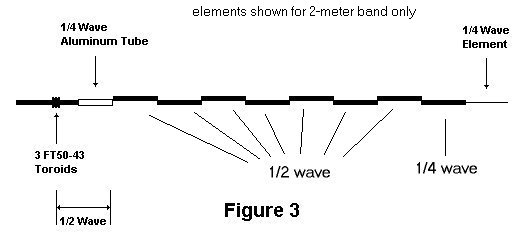
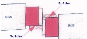
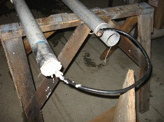
Starting with the bottom feed, make up the matching section, then solder (electrical) half-wave sections, alternating the center and shield for the ends. The image will better illustrate this method.
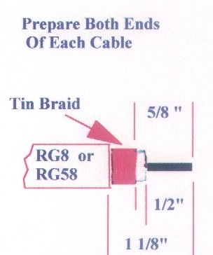
The top section is made from #12 or #10 copper wire. Solder a loop on the top end for hanging, later. The bottom "balun stub" is made from a piece of #14 wire or larger. Cut pieces utilizing the above formulas, plus 2-1/4". Cut 1-1/8" of black outer insulation from each end. Then tin copper braiding with solder. Using a sharp cutting tool or tubing cutter, cut 5/8" of tined braiding off each section end. Cut 1/2" of insulation from center conductor, leaving 1/8" between center conductor and braiding. After soldering all sections and balun stub together, check the return loss. Anything greater than 10 db is okay, however, best to get it above 15 db. If the formulas were followed, all should be OK. If not, trim or add to the 1/2 wave section(s). The more 1/2 wave sections you use, the more gain you get; about 6db gain with 8 half wave sections and 9db with 16 half wave sections. For down tilt, cut antenna sections 2% shorter than the calculated length and adjust for best return loss with the balun. For additional strength, the Author wraps each joint with thin wire, before the final soldering of such joint. If you have not done so, install a termination on the end of the "pigtail". The Author prefers type "N" male on the end of the tail.
After the performing check, finish antenna with the appropriate sealing against the environmental elements such as rain and snow.
Another person's version.........
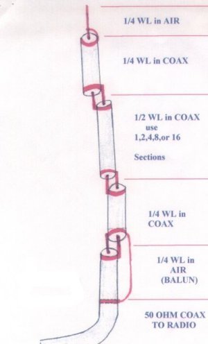
Note: Just to be clear, most of the images show for the 2-meter band. In this case there is seven 1/2 half wave elements, plus 1/4 wave ones on the top and bottom. For other bands (i.e. 1 1/4 meters) there will be a few more 1/2 wave elements in the middle.
When you get one or more finished you can install them inside old commercial "shell"s. Take apart the old guts of the commercial antenna you got and put the new antenna you build in its place. Taping pieces of foam will stabilize the elements nicely inside and keep them from banging around loosely in the wind. Check to verify the entire length of the antenna, including the pigtail (feed point) will match the shell. With the top whip near the top of the shell the pigtail should extend out the bottom from 12"~24".
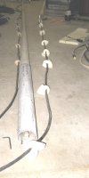
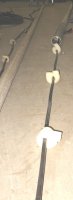
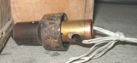
You'll need to secure the top end of the antenna with the top copper cap. Run a string from the top down the shell. Tie a nut on the end for gravity help. Or even a large bolt if you need more weight. A 1/2" usually works with most shells. Then tie the string to the top whip's loop. Use the string to pull the antenna up inside the shell. There will be some resistance as the foam spaces pass the first opening. Work it. Then remove the string. You now need to secure the top of the antenna with the top copper cap. To make a coupling, cut off about 4" of the old element and solder it up inside the top copper cap. Then drill a hole through the pipe for a string to run through. Make up a short run from the top of the antenna's loop to the copper cap. Use a few layers of string tied together for reliability. When you pulled the elements up you can use cheap, cotton string, but for the permanent "mount" you may considering using something better, such as nylon and a little on the thick side. Its a good idea to protect the string around the copper top's holes, since they have a sharp edge. One method is tape the string where it will be in contact with the holes.
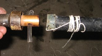
A recent, better way found in 2011 (thank you Doug) is a piece of tubing as a "grommet" as the right picture shows, preparing to size things up. Run the multiple layers of (strong) string though the tubing, then tied it together. To aid getting several strings through the tubing, try cauterizing them together with hitting the ends with a torch to melt them together. You may have to press them as it cools, with a glove so you don't burn your fingers. The Author does it without gloves because he's cool. Remember earlier you checked for proper length and fit inside the shell. Then pull the remaining antenna back down so the cap fits back on the shells top. If you did this correctly the top cap should fit on the top of the shell, with the pigtail running out the bottom as mention before.
>
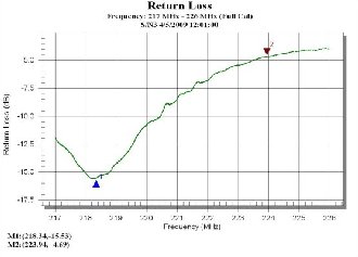
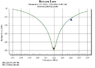
Before sealing you might want to re check the return loss. 10 db is an absolute minimum; SRG standards prefers a minimum of 15. The Author's building of antennas, if carefully performed typically produces ones with a R.L. of 20 db at the intended frequency. The left shows a prototype built for the Amateur 1 1/4-meter band in April of 2009. The RL shows 16 db, which is acceptable, however, being resonant at 218.200 MHz is cut way too long. The good news it's fairly easy to short up the elements, taking a hour or two, plus moving the bottom matching stub up a little. By a little, typically, 5 MHz represents about 1/4" at this frequency range so be careful. Some of this depends on the VC (velocity constant) of the coax you are using for this project. If you cut them too short you may have to start all over again with new coax. The right shows this antenna is resonant at the bottom of the Amateur band, so the cuts are going in the right direction. Also note the RL is excellent, being 29 db, which is way better than expected for this design. If this was cut just a little more on each element it would have been a perfect antenna match.
When you are satisfied with the resonance point (and RL) you can think about sealing the unit at each end against the elements of a remote site, such as winter's ice and snow and summer's bugs and bees. You can seal both the top and bottom; the next day you then can pack the completed antenna for your trip to the remote site.
For the top, pull out the cap a little and put some glue or RTV around the area, then push it back on. This will pull the array up inside the shell, so after sealing the cap pull on the bottom end of the coax to avoid any bunching. After cleaning of the excess glue let it dry overnight before (optionally) taping around the seam.
For the bottom you have a couple choices here. Regular foam can be pushed up inside the base to keep out most of the elements. Or you can permanently seal this area with that expanding insulation foam that comes in a can, with a spray application tube, around 1/4" O.D. It's believed that the foam does not affect the RF or impedance, however, has not been confirmed as of 2011. The three screws you removed earlier (for the old matching stub) provide easy access to insert the foam with that tube supplied. One small can easily does one antenna or two. Lay a piece of cardboard on the floor to catch the drips. Shoot enough foam so it starts to ooze out the bottom end.
TIP:
If you forget to cover the floor, or it makes a drippy mess don't touch it. Trust the Author; its a very messy task cleaning up wet foam. Let it dry overnight; to a semi-hard, crunchy foam, which is easy to cut and trim off the base. For the floor drips you can "flick" them off the floor, like a dried booger, LOL. It's also highly recommended you use disposal (painting) latex or similar gloves for this sealing task. The one picture shows how to position the coax with other items in the area to permit a good centered seal.
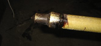
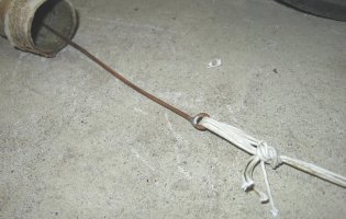
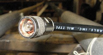
SRG standards call for these antennas to have a coaxial "pigtail" of minimum length of 18", terminated with a type "N" male RF connector. It also calls for the tower transmission line (LDF4, LDF5 or LMR400, etc.) to be terminated with the mating N female connector. This allow the best flexibility of any type of connector you may encounter on the tower. For example, if the existing transmission line is already an N male and its not practical to change it to a female, a barrel (fem-fem) has little effect on the impedance and is a high quality connection. One picture shows a typical and correct termination of the antenna end. Most commercial antennas come with this arrangement, especially the top end ones.
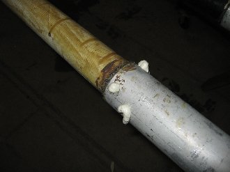
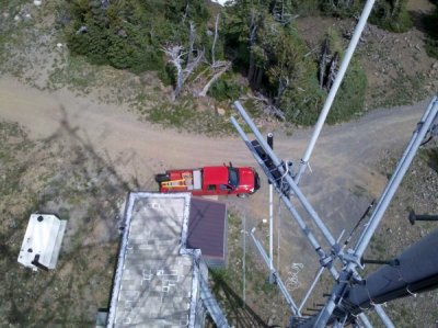
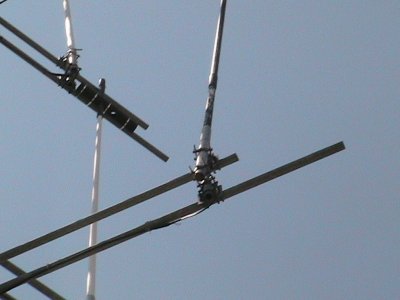
The pigtail also makes it easy for the installer to connect and seal this to the transmission line on the tower. This is especially true for offset (tower side mount) antenna install requiring the installer to hang way out from the tower's leg for this task. The pictures may not impact the reader how dangerous it is, but the Author can testify first-hand it very unnerving to hang out away from the tower with nothing but space under you. These pictures were taken about 100-feet off the ground at an extreme site in the Washington's cascade mountains. Also, note the way the top of the antenna is secured with a piece of 4" ABS pipe. Without top support its just a matter of time the 200+ pounds of ice sticking to the antenna will destroy it.
![[SRG home Direction]](images/srghome.gif)