Establishing a Jetting Baseline
Regardless of whether your sled is bone stock or you have
added some accessories, one of the most important pieces of information
you need for consistent peak performance is to establish is a “jetting
baseline”. This is when you fine-tune and jet your carburetors for a
specific set of conditions. Once you determine a baseline for your exact
intake/engine/exhaust combination, you can use the data to properly
calibrate your jetting for whatever conditions you may ride in. This
procedure is especially valuable for unique combinations that deviate from
the factory supplied jetting charts.
You will of course want to start
with the jetting recommendations supplied by the manufacturer for your
exact model. Normally, your sled will be jetted for conditions colder than
what you’re likely riding in to maintain a “safety margin”. If you have
added aftermarket accessories, follow the recommendations supplied by that
vendor. If they do not supply any suggestions, always err on the rich
side.
While more precise tuning can be performed using exhaust
gas temperature gauges, you can perform very accurate tuning by simply
analyzing the spark plugs and the piston wash. Many tuners will simply
learn to read spark plugs, as this is clearly the quickest and easiest
method.
At the time of your testing, air temperature and
elevation, at a minimum, are required to determine your baseline
specification. Better yet, what you’re really interested in is Relative
Air Density, a reading that is a combination of air temperature and
barometric pressure. You can determine the proper jetting for your sled at
a given temperature and elevation, but if this was performed when a low
pressure air mass was present, you could be too lean at that same
elevation and temperature if a high pressure air mass passes through. A
higher barometric pressure means that the air is denser, and there will be
more molecules of oxygen entering your engine, thus a leaner fuel/air
mixture.
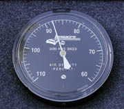
An air density guage can bepurchased from most leading performance shops. (Part #725-160 for $129.95 from Hi-Performance Engineering at (218) 681-2390 or (800) 451-5268
Make sure your machine is good and warmed up by running
it for a while before beginning any calibrations. You want to safely
operate the machine at wide-open throttle for at least 1/4 mile on a flat,
well packed surface. While at full throttle, shut off the ignition before
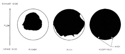
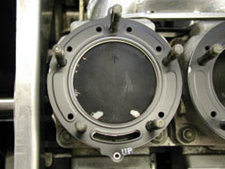
releasing the throttle. When the sled comes safely to a stop, examine the
spark plug color, piston domes, and even the exhaust manifold to determine
if the mixture is rich. Because of the differences in engine designs and
hundreds of performance products available for these engines, you may want
to contact a dealer or performance company that is familiar with your
engine combination and talk to them about any specifics you should be
aware of when “reading” your plugs and pistons.
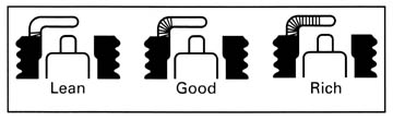
Generally, if the
spark plug insulator (white porcelain surrounding the center firing
electrode) is dark brown or black, the mixture is too rich. Hopefully you
are familiar with the desired color you’re looking for; it could best be
described as the color of cardboard, a light to medium brown. Very light
brown, gray or white is too lean!
Another valuable indicator on the
spark plug is the center firing electrode; as the plug color starts to
lighten up when properly jetted, the center firing electrode will start to
have a “silver” tip, or crown. As the mixture becomes leaner, this silver
crown will start to creep down the side of the electrode; this is your
target. This metallic appearance on the end of the electrode should not
extend any further than 1/4 - 1/3 of the way down the tip. Many tuners are
happy with the margin afforded by simply seeing the silver tip; then
they’re close enough for trail riding with a bit of margin to spare.
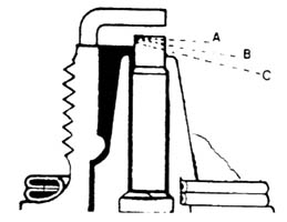
The ground electrode is also an indicator; on many
engines you will see a “shadow” (darker area) just up to the radius (bend)
that will usually coincide with the color and firing electrode appearance.
If this shadow is further down the ground strap towards the plug threads,
you’re likely too lean. If this dark shadow is all the way across the
strap to the center of the plug, you’re too rich.
Use all three of these plug indicators; try not to rely
on only one. Color is likely the easiest and most widely used, but looking
for the metallic crown on the tip of the firing electrode is a very
accurate indicator on most engines; just don’t ignore the other
indicators. When experienced, many tuners can recognize a properly jetted
sled simply by listening to the tone of the engine. They always verify
their instincts, but they can get really close before they perform final
fine-tuning.
(This same procedure can be used to tune the needle
position, but you would want to maintain a 1/2 throttle position for a 1/4
to 1/2 mile, again hitting the kill switch before releasing the throttle.
This distance will ensure that the color you are seeing is caused by the
carb fuel circuit that is responsible for that throttle position.)
It
is best to reduce main jet sizes very cautiously and carefully to avoid
piston and cylinder damage. If you are way off, reducing the main jet two
sizes at a time may be acceptable, but once you start to get close, only
reduce the mains one size at a time. When the engine performance is clean
and the spark plugs reach your desired state of tune, record your
environmental conditions. Again, at a minimum, record the temperature and
elevation. Better yet, the Relative Air Density (if you have access to a
gauge).
Now you have established a baseline. Anytime the elevation and
/or temperature (air density) changes, you can compute the changes needed
to your main jets to maintain a similar state of tune. There are several
mathematical systems available to properly determine the required change,
so we’ll cover some of them.
Relative Air Density
This is
going to be your more accurate method. The higher the state of tune your
machine is in, the more seriously you should consider this method. Let’s
say that when you get your engine running cleanly and the plugs are
looking right, you were using 360 mains and recorded the air density at
80%. Next weekend you find the air density to be 88%. You know you have to
jet up, but how much?
Divide the “new” air density by the “old” air
density, then multiply this factor times the “old” jet size. This would be
88 (new density) divided by 80 (old density) which is 1.1; multiply this
times your old jet size (360) and you get 396. Rounded up (5 and over
round up) to the next jet size, you will need to install 400 mains to
maintain your fuel/air ratio. It’s that easy.
Temperature/Elevation
The
majority of tuners will simply rely on air temperature and elevation, and
for stock machines this method is tried and true. If you know the main jet
size that was right on the money for a given elevation and air
temperature, you can use “Jetting Correction Charts” to mathematically
determine what changes will be required to maintain your state of tune.
Arctic Cat uses a “Temperature/Barometric Pressure Chart”, Ski-Doo
references a “Carburetor Main Jet Correction Chart”, both of which can be
found in their respective Racing or Performance manuals.
Holtzman
Engineering has generated a set of “Jetting Factor Charts” which are
extremely valuable. These charts provide a “jet factor” for different
altitudes and temperatures. This “factor” can be applied to any jet size
at any given altitude and temperature to arrive at the correct jet at any
other set of conditions. This factor includes the affects of the pilot and
needle jet on the overall total fuel delivery.
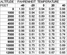
JETTING FACTOR vs. ALTITUDE
AND TEMPERATURE
MIKUNI HEX JETS
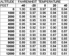
MIKUNI ROUND AND KEIHIN HEX JETS
Once again, an example might help. Let’s say we have a
Mikuni hex main jet installed of size 300 and the sled runs well at an
altitude of 8000 feet and –20 degrees F. What size jet would we need for
an altitude of 3000 feet and +20 degrees F? The Mikuni hex jet factor for
the first set of conditions is 0.79; that for the second set of conditions
is 0.85. The formula is very similar to the Relative Air Density formula;
“new jet factor” divided by “old jet factor” multiplied by the “old jet
size” equals “new jet size”. The new jet size therefore is 0.85 (new jet
factor) divided by 0.79 (old jet factor) times 300 (old jet size) equals
322 (new jet size), so we would use a size of 320 to maintain a similar
fuel/air ratio.
If the carburetor had been a Keihin with a hex jet
size of 160 at 8000 feet and -20F, what size jet would get us to 3000 feet
and +20F? The jet factor for the first set of conditions is read from the
graph on the right above and is 0.89; the factor for the second set of
conditions is 0.92. The new diameter numbered jet size is therefore
0.92/0.89 * 160 = 165.
Needles are usually moved one clip for
approximately every 20% change in Mikuni hex jet size or every 10% change
in diameter numbered jet size (Mikuni round jet or Keihin hex jet). For
temperatures or elevation in between these charts, it is fairly
straight-forward to determine the proper jet factor. The jet factor for a
Mikuni hex jet at a temperature of –10 at an elevation would be between
0.85 and 0.83; that would be 0.84.
Holtzman has also developed jetting
charts that display required jetting reduction as a percentage for use
with their Tempa-Flow and Vari-Flow float-bowl pressure regulator
compensators that are capable of changing the effective jet size; a
combination of the needle jet, main jet and pilot jet. These devices
compensate all the way down to 1/4 throttle by changing the pressure
across the jets, a very effective method of broad-band jetting correction
very similar to the method used by the Ski-Doo DPM system.
Many
engines with broad fuel curves (like most Yamahas) will not make any more
power as you jet down from a certain point, and basically make the same
power across a three-four jet size spread. Another consideration is that
an engine under heavy load will require more fuel; riding after a wet,
heavy snowfall will require more fuel for otherwise identical conditions
than a flat, hard surface. Your engine will also run cooler and safer if
you error slightly on the rich side. Error on the lean side and you could
find yourself walking home or hitching a ride.
Once you have properly
jetted your sled once and know the conditions, you can use that
information to determine the proper jetting for just about any different
condition you may ride in. You can also use these formulas to determine
how much of a safety margin you may have for a given set-up; if you know
what jetting really makes ‘er sing at 0 degrees, you can easily figure out
how far you have to jet up to be sure you are safe down to –30, or
whatever! Use this knowledge to be your fastest when needed (competition),
and to give yourself some margin when you need it (longevity). Remember to
always check your specific set-up with piston, plug, and/or EGT readings,
and start out on the rich side and work your way down.
Snowmobile Jetting
Procedure
by Allen Roberts, Starting Line Products
One of the best field jetting procedures comes from Allen
Roberts, a leading calibration technician with Starting Line Products in
Idaho Falls, Idaho. Starting Line Products provides very detailed
calibrations specifications with their performance products, due in part
to the testing procedures.
“Before performing a jetting calibration,
the fuel system must be inspected for cleanliness and the carburetors
should be checked for proper float height setting. Another very important
item is carburetor synchronization. If the carburetors are not properly
synchronized, the throttle response will be very poor and this can lead to plug
fouling. I prefer to use the “Uni-sync” carb synchronization tool
(available through SLP for $36.08, part #20-81). Using the Uni-sync,
adjust the idle screws to synchronize the carburetors at idle. Loosen carb
cable adjustment to ensure slides are bottoming on idle screws. Then check
that the throttle slides are moving from the idle screws at the same time
when the throttle is opened. If throttle slides are not opening together,
lengthen or shorten the cable adjustment at the top of the
carburetors.
The low speed tuning (idle to 1/4 throttle setting) is
calibrated by pilot jet changes and adjusting the air screw. Operate the
throttle between idle and 1/4 and see if the engine revolutions increase
smoothly. If the pilot jet circuit is too lean, increase in the engine
speed will be slow and irregular. If the pilot jet circuit is too rich
this would create heavy exhaust smoke as well as a dull exhaust noise. If
you cannot maintain speed in this 1/4 throttle area while the throttle is
held constant, the pilot jet circuit is too lean.
To find a good
starting point on the air screw, warn up the engine to operating
temperature and adjust the air screw in (richer) or out (leaner) until the
idle RPM is at its highest point (do not open more than three turns). One
point to watch on air screw adjustment, if the engine idle to 1/4 throttle
performs best with the air screw adjusted 1/4 turn or less it may be an
indication that the pilot jet is too lean and the opposite holds true if
the air screw ends up near three turns the pilot jet may be too rich. It’s
easier to adjust the airscrew than to change pilot jets to find out if you
are too rich or lean on the pilot circuit.
The mid-range tuning (1/4
to 3/4 throttle) is calibrated by the needle jet and jet needle. The jet
needle tapers off at one end and the clearance between the needle and the
needle jet increases as the throttle valve opening gets wider allowing
more fuel in to the carburetor venturi. The air-fuel mixture ratio is
controlled by the height of needle positioning clip that is inserted into
one of the five slots provided in the head of the needle. The top slot #1
is full lean; the #5 slot is full rich.
The needle jet is changeable in
most Mikuni carburetors. The fuel delivery can be adjusted by changing to
a larger or smaller inside diameter, the size designation will have a
letter followed by a number example, P-2. The number shows the inside
diameter size in increments of .010 mm. Example, the difference between
P-2 and P-4 is that the inside diameter of P-4 is .010 mm larger than P-2.
The letter shows the inside diameter size in increments of .050 mm, the
difference between P-2 and Q-2 is that the inside diameter of Q-2 is .050
mm larger than P-2. So a larger diameter needle jet will allow more fuel
to pass or a richer mixture.
Dialing in the pilot circuit can normally
be accomplished by listening, seeing and feeling what the sled is doing,
but above 1/4 throttle the horse power and engine loading is increasing
rapidly and the chances of engine damage because of improper jetting
increase as well. So it becomes necessary to start reading plug and piston
color. The best way to get a valid piston/plug reading is to hold the
throttle steady at what ever throttle setting you want to check and run at
that setting for at least 1/4 mile if possible, kill the engine before
releasing the throttle.
A couple of tips on mid-range jetting, start
out conservative, it is easier and less expensive to change jets than a
seized piston. Use the jet needle for changing fuel requirements first;
it’s faster to change the "E" clip position than to change the needle jet.
If you find yourself at full lean or rich and still needing more or less
fuel that is the time to change needle jets. A rule of thumb here is one
"E" clip position on the needle is equal to one needle jet size. So if
your needle jet is a P-4 and the needle "E" clip position is #1 you could
change the needle jet to a P-2 and move the needle clip to #2 and the fuel
flow would be real close to the same as the P-4 and #1 clip position.
The tuning procedures for the main jet are the same as the mid-range
except the throttle range will be 3/4 to full and of course you will be
changing the main jet not the needle jet or needle.
After you have
completed jet testing and are happy with the results, you would record the
air density (or temperature, barometer and elevation) for that day. This
will be your “base air density” and “base jetting”. When the weather
and/or elevation (air density) changes use the Relative Air Density
formula or a jetting correction chart to determine the proper jetting
change.”
Starting Line Products can be reached at 208-529-0244 or on
the web at www.startinglineproducts.com. They specialize in designing,
manufacturing and calibrating performance products for snowmobiles.
This Article is produced by SnowTech Magazine. Bill Infanger has givin me permission to reproduce it on this site for the benefit of others to learn. Further reproduction, including newsgroup is not permitted without permission of Snowtech Magazine. Click on the above link to contact them and please visit their site, as well.
![[Kar's sled page]](images/winter_home3.gif)