Yagis for both bands

Introduction

This was a design started about 20 years ago. It's a three-element yagi beam with a gamma match. The match (change from original) now is (DC) directly coupled to the driven element. This helps dissipate static. The original design was a light duty type, using brass welding rods for the elements. While that version is actually easier to build and fine for in-town sites, a more stout version was developed by the Author in 2007. Therefore, this page will covering the heavy duty which is good for high sites, particularly with ice loading.

Here's your shopping list from the local hardware store:

  • One stick of 3/4" L thickness copper pipe (30" for the boom).
  • About 80" of 1/2" copper pipe.
  • About 12" of either 3/8" or 1/4" copper pipe (hard drawn is best). Also, in the case of 1/4" soft pipe, the outside diameter of that size is about 3/8", as not to be confusing, enough.
  • One 3/4" end cap.
  • At least two 1/2" end caps (six is best to seal all three elements).
  • Some misc stranded wire (20-24 gau is fine, you'll be stripping the insulation off).
  • One RF chassis connector (choose whether UHF or N type female).
  • About 2 foot piece of RG-58/U coax.
  • Propane torch, solder and eye protection. (Author uses regular electronics 60/40 tin/lead, rosin core type).
  • A bench, vice and drill press will help.
  • Some sealant

    For this version you'll be using 1/2" pipe, instead of the (wimpy) rods. The matching section (pipe/tubing) can be either 3/8" or 1/4", and it will go into the (1/2" pipe) driven element, but only on one side. Therefore, depending on the size of pipe for the match, you'll need some additional parts from the hardware store:

  • One 90° elbow
  • One end cap.
  • One short stick of pipe (they come in 1-foot) lengths

    These drawings show the dimensions for the light duty version; the notes on the drawing spec the welding rod, however you will be using copper pipe, instead, for the elements. To enlarge the image, them click on them. The picture on the left is for the 1 1/4 meter band, while on the right is for the 70 centimeter band. Since the former is half the frequency, all sizes are double of the latter. This makes it real easy to remember. The original file is available upon a modest donation as well.

    Since this page is for the heavy duty, there are some differences , mainly in the elements for the 1 1/4 meter version. Following these sizes will put you in the middle of the band. For the prototype the Author found center (best return loss) at 224.50 MHz. Remember the 70 centimeter version has not yet been built or tested in the heavy duty version; only the light version. Also, the reason for the elbow on the match is the tubing will collapse if you try to bend it in that small radius.

  • Reflector is 26 1/8"
  • Driven is 24 1/4"
  • Match is 7 1/8", with 2 1/8" wide (away from driver)
  • Director is 23 3/4"
  • Spacing from Reflector to Driven is 10 1/4", on center
  • Spacing from Driven to Director is 9 1/8", on center
  • Therefore, spacing from Reflector to Director is 19 3/8", on center.


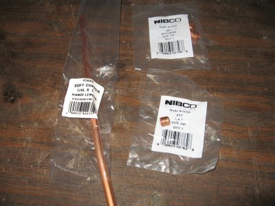
    Layout the parts. On the left these copper parts sometimes comes in packages. Shown is the "1-foot" packages length of either 3/8" or 1/4". The choice is given since some stores don't carry the 3/8". This will be for the matching part, discussed later. On the 3/4" pipe you'll need 30" (for the boom) but if you want to mass produce these antennas a good number is a batch of four; one (standard) 10-foot stick will make four booms ( 30" x 4 = 120" = 10 foot).


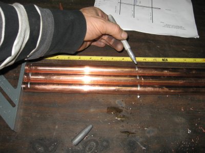
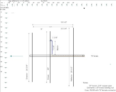
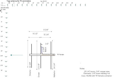
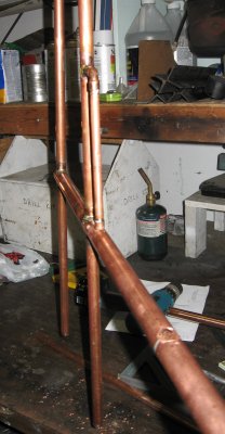
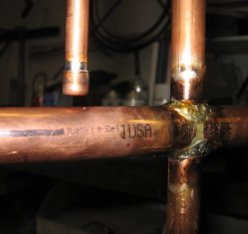
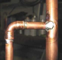
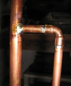
    Cut the (1/2" pipe) elements to length as just discussed. Drill the holes in the boom for them. Pipe is weird. For the "1/2" inch pipe the O.D. is actually about 5/8", so that's the size of hole you'll need to drill into the boom, for the elements. Using a drill press helps keep the holes straight and level, so the elements line up in a row when inserted into the boom. Same goes for the match; if you use "1/4" inch, actually you'll be drilling about a 3/8" hole. For the match; take the (3/8" or 1/4") small pipe and solder a 90° bend, then inserted it into the driven element, while leaving about 1/4" space on the end to the boom surface (so they don't touch). The right picture is not at the greatest angle, but gives you the idea.


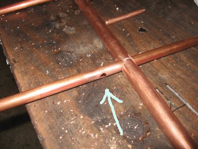
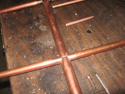
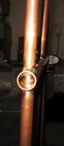
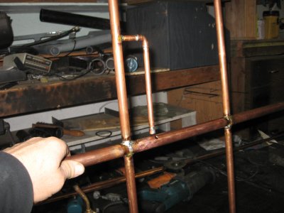
    The reflector will have it's own (1/4") hole drilled in the center. This is to let the coax run past it, while on it's way to the driven element. The left picture shows this and the right shows it pushed (and center) inside the boom. Remember to center the other two elements then solder them in.


    The front of the boom (on this version) ended up being closed, but you still can cap it to be sure.


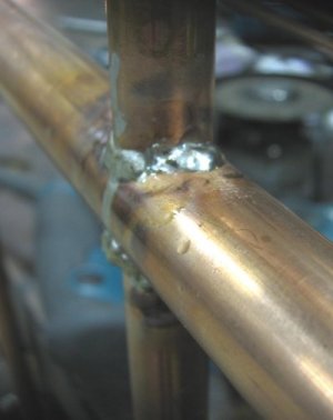
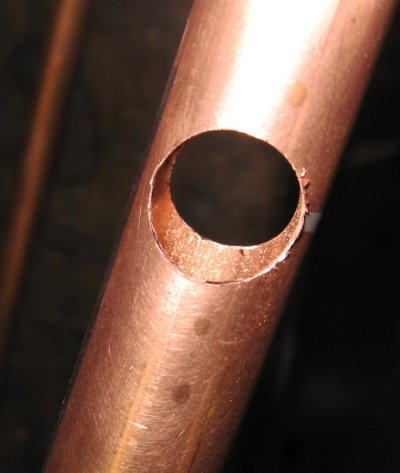
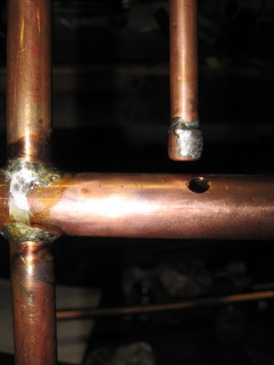
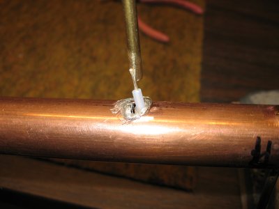
    Here's a close up of the matching section. For the 3/8" pipe, using a 25/64" drill bit works great. Remember to drill the hole only on one side of the (1/2" pipe) driven element. This will produce a "clean" surface around this (RF current) junction point.


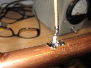
    For the bottom part of the match, install the end cap. This will help soldering on the (hot end) of the coax. Also, you might consider capping both ends of the driven element, since water could migrate into the matching section, ending up at the bottom (the cap) and freeze in the winter.


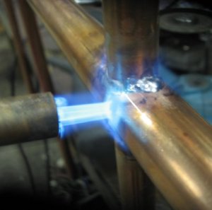
    Then dress and solder the coax center to the matching end and the shield to the boom's surface. Even though the picture shows teflon coax, any RG-58/U will be fine. Use the non-foam to avoid melting the dialectic. This picture shows the light duty version but the install is pretty much the same for this part. This is a tricky task the first time around. If you need more details or get to using larger coax (RG-X, etc.) click here for a lot more pictures. It shows pictures for the light duty version, however should give you the ideas you need for this version.

    p>


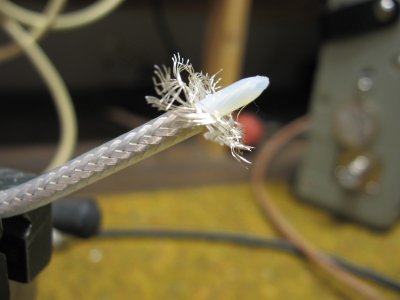
    Then you can seal this area with epoxy and/or RTV. Use the non-corrosive RTV. Dow Corning make a good one, called "748" RTV. For information on this product click Here for the PDF file. (right click and "save as") Also, just discovered is a more "electronics friendly" version is the " 738 " type. Either type probably will work fine.

    If you have trouble finding a tube you might try these distributors including some around the Spokane area. It's a big list (PNW) so you'll need to scroll down for your city. Also, it was pasted from some site with no time to make it "pretty" to read. (as is).

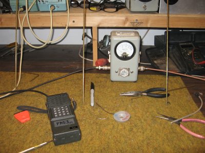
    Test the return loss (VSWR) as it should be more than 20db. Front to back should be better than 20 db as well. This last measurement was performed indoors, therefore is not conclusive. For best field strength measurements you should be outdoors with no buildings (especially metal) within 100 feet, preferably more than that. The Author has a 10-acre area for this purpose.


    Other notes:

    The heavy duty version has not yet been built or tested on 70 cm band; only the 1 1/4 meter band.
    The materials will weather fine. Present yagis have lasted more that 20 years outside.
    If you feel compelled to paint, be sure it's not a metallic bases (some oil paints) for obvious reason.


    [SRG home Direction]