The following rules are observed:
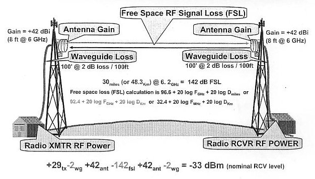
System Gain (3 ds3 radio example above):
As in the case of VHF-UHF Amateur RF paths this can be somewhat simplified. More specifically, would be Amateur RF links.
A -88 dbm is enough signal to produce a good quieting signal into a modern FM receiver since most are spec at -115 dbm sensitivity, or better. Having said this; it's also good to attemp stronger signals for improving the fade margin.
Fade Margin
Fade Margin (FM) is the difference between the RSL and the squelch point of the far end receiver. For practical circuits the receiver should "fail" the circuit in the event the path drops enough to raise the noise floor in the detected audio no more than a 20 db signal to noise ratio, or a 20 dbm0 noise floor. With most modern LMR receiver's this would be around a -100 dbm RF level. Therefore, if this was observed as a standard squelch point the (above) RSL of -88 would produce a FM of 12 db. To note, SRG specs call for a minimum FM of 20 db; 30 db being desirable.
Another notable RF propagation study is the reception of a distorted signal. This occurs when a receiving station is hearing more than one path from the originating source (far end transmitter). With reflections from terrain or metal structures (buildings) producing multi paths to the receiving station, hence, causing a distorted signal received. This is especially noticed in the LMR/amateur operations running FM mode.


![[SRG home Direction]](images/srghome.gif)