Converting the Motorola MX-350 series HT for link radios
Introduction
This document is written in attempt to include everyone interested in serious construction of a quality product.
Its rather technical, however, if you have a basic electronics background with some repeater building experience this should not be an issue.
Understanding schematic drawings is required.
Should you feel qualified you are welcome to deviate from the Author's design.
If you are new at the repeater operation you might want to check out additional technical books relevant to this documentation.
Allow plenty of time to construct each radio, especially the first one.
No free technical support is available, however, some printed documents are available on an occasional bases, for a modest cost for P & H.
The project is designed for Amateur Radio (not commercial) and is open for discussing, changes and improvements without notice.
About this page
Several images (pictures) on this document, while on-line are enlargeable simply by clicking on them.
This gives you an opportunity to "zoom in" for better details should you need it.
Other images are not large, to save room on the server.
Some images on this page show only general practice and may not be the completed product or bear accuracy.
Some links (that you click on) within this page open new browsers, while others permit you to hit your "back" button.
Reports from readers can go either way on this method of navigation.
This document is best viewed with I.E. 5.0 or later with your screen set for 1024 x 768 or higher resolution.
There are other variables for printing this document such as screen resolution, font setting, view and zoom settings, your monitor type,etc.
Apologies; time did not permit building this document to be completely friendly with other browsers such as Firefox, Netscape or Opra.
You are permitted to copy, print and distribute this document for non-profit use while keeping the Author credited.
The contact information is on the main page of this web site.
This is brought up to clarify the final product may be finished without documentation and may vary from what you see here.
Acronyms, Definitions, and Theory basics:
Amateur Radio is to develop the art of radio and improving operating practices.
This can set a good example for others, including the commercial industry, to what Amateur Radio system(s) are capable of doing to provide public service
communications in time of need.
This includes the technical side, to produce good operating repeater.
To be very clear on this philosophy, we will start with very basic theory.
"Two-way" Radio systems send intelligence (voice, data, etc.) by modulating the originating transmitter and decoding (detecting) this modulation at the far end
receiver back to something usable to be understood.
How well this is understood depends greatly on how well the system is set up.
Just about anyone can "throw" a system together to make it work, somewhat.
SRG design specifications call for a better way as you will see in this documentation.
A typical (commercial) system uses the audio portion of 300Hz~3KHz for modulation of Radio Frequency (RF) in various modes (AM, FM, SSB, etc).
This document covers FM only. Levels will be somewhat different than you may be used to. Also it calls for good technical management.
For one, technician organization and discipline is necessary. Plan on what you want to do for a system design and stick to it.
Force yourself to keep good practices. One good practice is to establish level references. Some call these "benchmarks", or "baselines".
While old Amateur methods used linear (volts, watts, etc) units of measure, most SRG designs and operations use logarithmic units in "dbm" for audio and RF.
Once accustomed, it's easier to see the entire picture this way, when designing a system, checking frequency response, and keeps the guesswork
out of troubleshooting a subtle level problem.
More information on this subject can be found by clicking here.
References can be expressed in a few acronyms.
This is very dry reading, however, you need to spend time on this to better understand advanced circuits, later on.
Normally, a tone of 1 KHz (sometimes 1004 Hz) is used for a testing a "2-way" VHF-UHF transmitter or receiver.
TTL ( Test Tone Level ) is referenced to 100% system modulation; in this case F.M. (Frequency Modulation).
FM is also referred to "deviation" (of the carrier, at an audio rate).
For Amateur Radio 100% system modulation is normally + - 5 KHz.
Other areas/States and/or commercial services have different bandwidth standards, presently.
In that case it would be + - 2.5 KHz. For this documentation we will only cover the former (5 KHz deviation).
TLP ( Test Level Point ) refers to a measurement point, on equipment, in the system, in reference to TTL.
TLP provides easy reference to any parts of the system for measurement and alignment. 0 dbm is referenced to 1 milliwatt at 600 ohms.
Therefore, a transmitter AF input with a TLP of 0 dbm, with a TTL of 0 dbm tone input, would fully modulate the system.
If the far end receiver was set up the same its output a 0 dbm tone as well.
A 6 db drop in (voltage) level would reduce the modulation in half, and so on. In general, levels are stated in transmit-receive (Tx-Rx) order.
Therefore, an audio (VF) "drop" TLP of 0/0 would mean a Tx TLP of 0dbm, Rx TLP of 0dbm.
Absolute levels are specific-measured (operating) levels, not to be confused with TLPs.
Sometimes operating levels are not at TLP.
In this case a level would be so many db "down" from TLP, or just called "xx down".
For example, CTCSS tones normally are 18 db down. (1/8 deviation from voice, or 18 db down from max-voice).
To avoid technician confusion two sets of numbers are sometime used in diagrams and on the physical equipment's ports or I/O connections.
Figures in parenthesis are the TLPs.
Non-parenthesis figures are (absolute/actual) operating levels, and as mentioned before, may be at different levels from the TLPs.
Levels below 0 dbm are negative, while above are positive. Take this into consideration when working with system gains or losses.
Normally the negative levels have a minus in front of the number, while positive have a plus sign.
This is also true for absolute levels (as opposed to TLPs).
For example, most base/repeater station's transmitters run a +42 dbm, while portables and other lower power links run about a +30 dbm, some less.
The station's receiver has a typical sensitivity around a -117 dbm for 20 db quieting.
These levels are at the transmit and receiver ports.
Also known as "TOR" (Top Of Radio), AKA, Top of Rack is before the transmission line and antenna outside on the tower.
The latter parts can be figured in for the entire system's losses or gains.
Single digit numbers of "1" and "0" in parenthesis are not to be confused with TLPs.
In this case these 1s and 0s identify the logic state of a gate, or other TTL/CMOS I/O driver circuit, and so forth.
Another aid to avoid confusion between logic states and a TLP is that the latter normally would have a " + " or " - " before the number.
For example a TLP of -14.8 is the audio input controlled by a logic gate of [1], being a normal logic "high".
One last word on the logic state. The parenthesis indicates a state in normal standby/no activity condition.
Other definitions, acronyms and other "shortcuts" are used, once the subject is established.
This is for practical reading. For example, in the parts list several manufacturers are listed.
To save space the name is truncated. For example "Mouser" is for Mouser Electronics, a major parts supplier.
Overview
For this project the Motorola MX-series portable in the Amateur 70cm band is used.
This project is support equipment for Spokane Repeater Group.
This equipment works in the "background" for managing user signals to a control point of the Author's repeater.
The MX radio
The Motorola MX-350 (35x) radios were produced in the 1980's and performed very well as portable units in the 150, 450 and 800 MHz bands (VHF-UHF) for
commercial and government services.
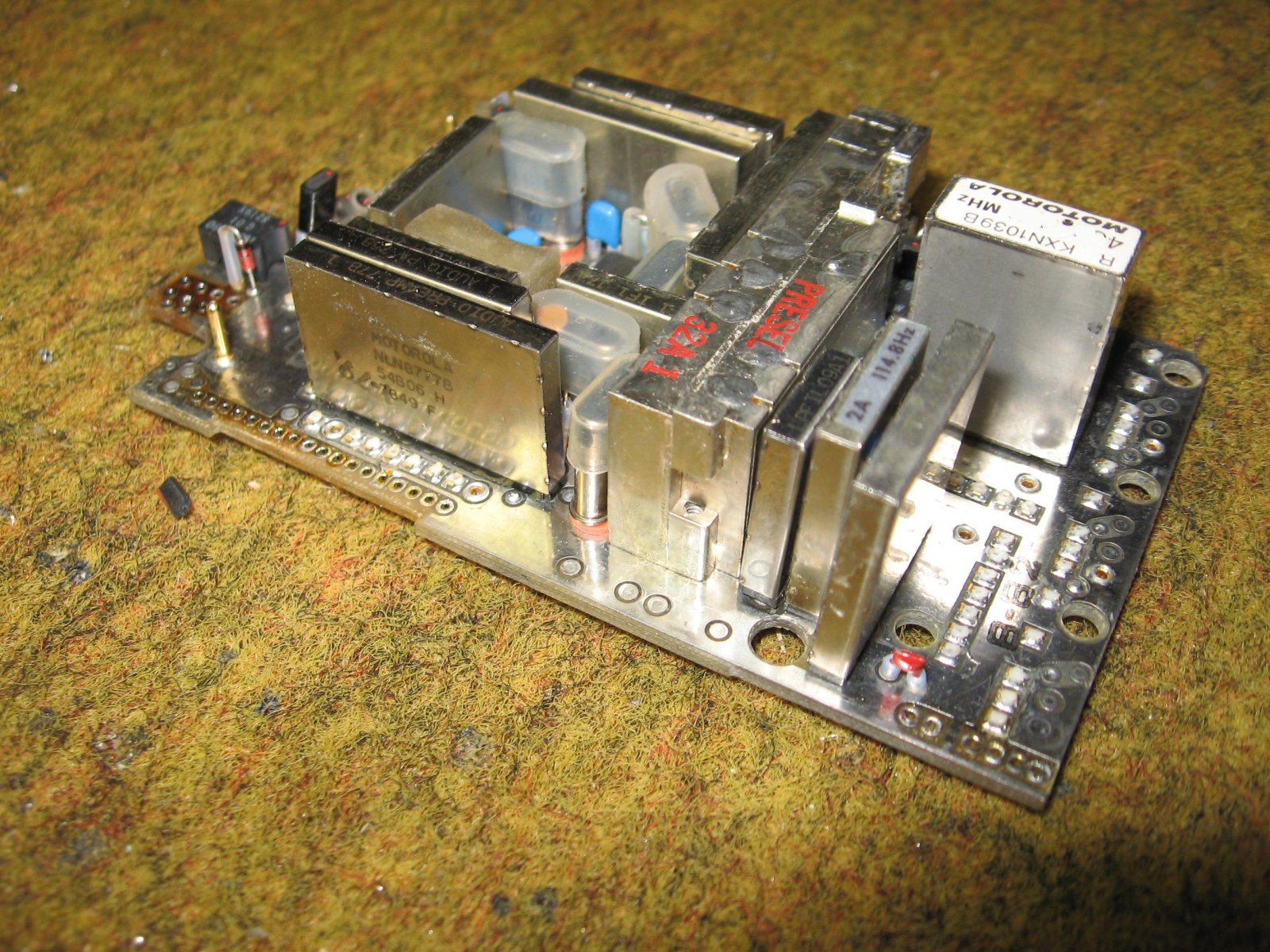
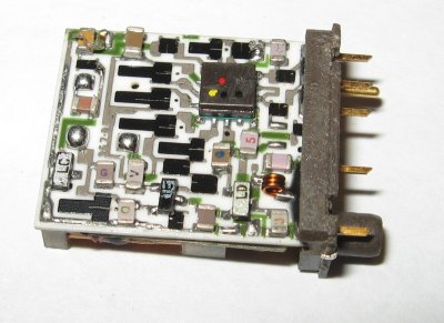
One distinct feature of this radio is modular (units) inside, plugged into a mother board.
The radio came in the "2W" or "5W" version, with 1-8 channel, PL or DPL, or even "DVP/DES" encryption.
Both transmitter and receiver performance is good and (basic) frequency response is very good as well.
As usual, the transmitter does not need any frequency compensation; only the receiver, which is minimal.
The receiver's a single conversion with an I.F. of 21.4 MHz.
Since this project is about the 70cm band we will be covering the UHF model only.
The Channel element (crystal) situation:
For SRG these link radios "talk" to a central HUB repeater. The HUB is on a 70cm conventional pair, high in, low out.
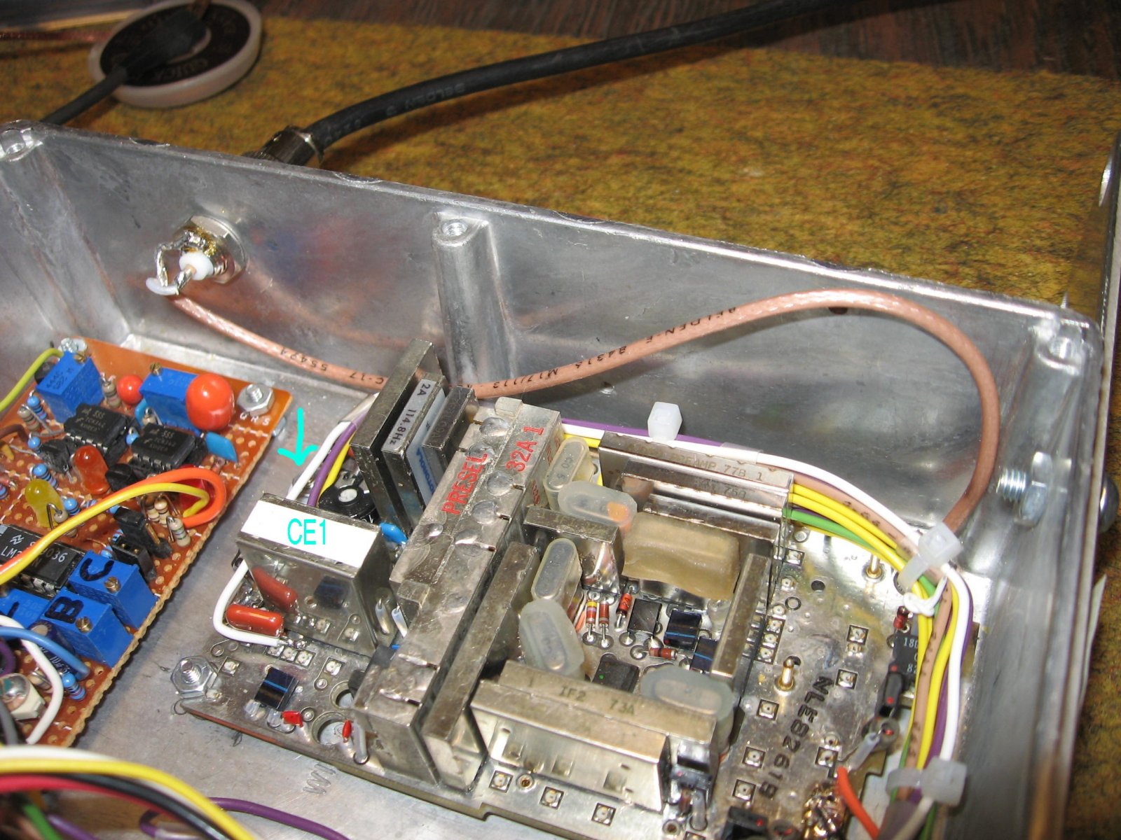
For receive only (uplinks) the radio uses one channel element (CE1) and is crystaled for the operating frequency.
For transmit only (downlinks) the radio uses CE1, plus a second element for transmit "offset".
This offset (from the receive frequency) can be 0 MHz (simplex) or +5 MHz (repeater) called CE101 and CE102, respectively.
For SRG the uplink radios have CE1 crystal on it's operating frequency output.
Downlink radios use CE1 and CE102 to transmit the high frequency into the HUB.
Using CE102 also permits "robbing" CE1 for an emergency repair of another radio since either uplink or downlink radios use the same CE1 frequency.
This arrangement is similar to the UHF Micor mobile arrangement for Tx and Rx frequency control.
CE1 is part number KXN1039A and CE102 is NLE6972A. Only CE1 is needed when ordering recrystal.
Remember to send in the channel element for this for proper compensation and testing at the factory.
CE102 normally comes with the radio and does not need any changes.
Other parts:
For the receive only radio, several modules are removed (not needed) from the transmitter section.
For the transmit only most of the modules are left and needed.
To conserve heat (IR losses) the Tx unit's final power amp is removed and bypassed with a jumper. More on these arrangements later.
To properly mount and shield the radio, it was decided to strip it down to the main board, discarding several outside items, such as the case, controls,
flex boards, etc.
Because of this, a few parts needed to be mounted either directly on the main board, or (at least) the controls on the front panel,including the volume and
squelch controls,R308, R311 and C304, and C301 respectively.
The values for the capacitors where slightly changed, due to available parts at the time of a project package being built, as a replacement to a defective one;
the Omak uplink.
Normal and future uplink receivers will use the stock 0.0047 uf and 0.27 uf values, respectively. Also, the volume swap resistor, R309 was left out.
This is a circuit to prevent the speaker volume from being turned completely down, for portable use and not repeater use.
For this unit, these controls were mounted with solder and glue on the bottom end of the board.
A "7.5" voltage regulator needed to be added to permit the package to be powered directly from a standard +12 DC supply.
A 7808 was selected (+8v output) which was close enough, since most MX portable batteries run 8v just after a charge.
No degradation or decrease in reliability was noticed with any of these modifications-deviations from stock specifications.
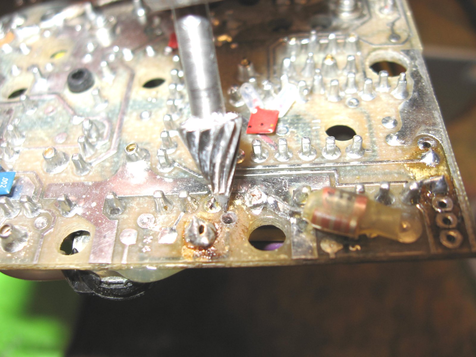
The main board has three convenient mounting holes; however, some modifications around two of them might be needed.
That is, cutting (or lifting) a run near CE'4s pin 7 which is the +4.6 line, and perhaps the +7.5v line on pin 6 as well.
This prevents shorting these lines to ground when the 4-40 nuts are tightened down.
The OEM manual says pin 6 is the "T2" (+7.5 XMIT mode only).
With JU62 in, it also has this voltage during receive.
The run was pulled and the eyelet hole for the +7.5v line was reamed out with a dremel tool.
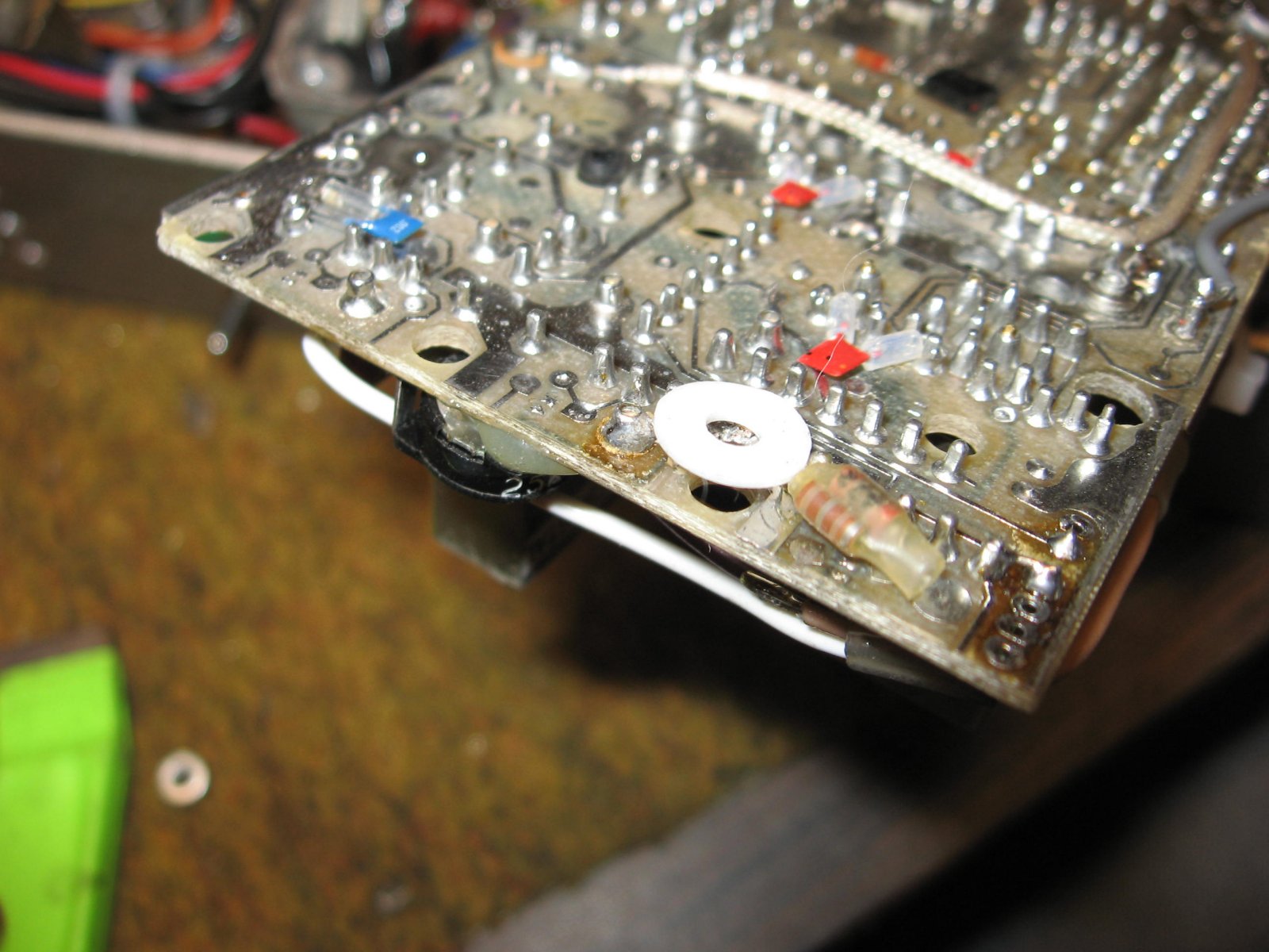
In addition, the one nut holding the hole near CE4 was further protected with an insulating washer.
The other two holes didn't need the washer, therefore, gave good ground connection to the chassis (box).
A good ground is needed to stabilize the MX radio.
During service and testing, while handling the radio "hot" expect some variances to performance.
The receiver has a good "cos" output on the squelch switch I.C./module U9, pin 4.
It's a high (+4.0v) during standby and goes low upon squelch open (or carrier activity).
If using the cos/af board, set it for this mode(active low).
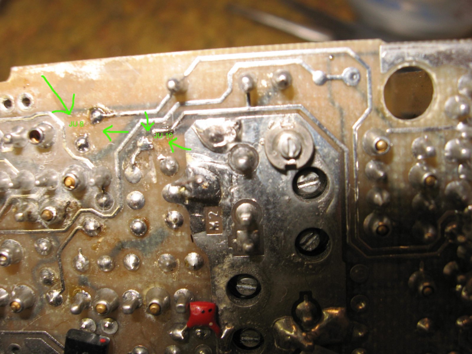
JU10 needs to be cut, so the PL (CTCSS) line from U133, pin 12 does not affect the MX squelch circuit, U7 pin 4.
Speaking of U7, JU11 is IN. (is out for selective call units, in portable service).
This U7 also regulates the +4.6 ("F") for other modules, therefore, is very important it's functioning correctly.
The speaker also needs to be on CS for local monitoring and testing.
The PL decoder section is left intact, because futures plans on tone protecting the uplinks.
In this case the uplink PTT line will be PL (tone protected) with the "and" squelch function requiring both a carrier and tone from the MCP to activate.
The COS/AF board will provide the PTT with an "AND" squelch for this mode; getting the cos signal from U9,pin 4, plus the PL Indicate (PLI) from
the previously mentioned U133, pin 12, which is a normally high (+1.5v) during standby and goes low upon a valid PL decode.
Diodes will need to be added to the cor/af board to form a "NOR" gate, thus making an "and" squelch gate, in effect (both inputs need to go low
before the circuit is active).
The repeat audio, however, will be on carrier squelch. This will eliminate any user signal decode delay.
The only slight delay would be the first key-up of the system for a PL decode, as mentioned from the MCP, which should be short, say around 100 msec.
JU 8 was cut, as well, however, after further investigation it was determined this was unnecessary.
JU 8 is used to override the portable's PL mode switch from line "P".
For the replacement project, of course, this feature is not used. It was left cut, to save time.
The discriminator, U6, pin 7 (otherwise tie-point E8) feeds the top of squelch pot, R311, the LPF, U123, the local speaker's audio module, U7 and now,
the COS/AF board input. The TLP is - 7 dbm.
During preliminary tests, this receiver performed the best for any brand of receiver for basic frequency response, audio detector distortion, and
sensitivity.
In a "pinch" the audio could be left straight out, however, this does not meet SRG's specification for response, therefore, only minimal equalization was
needed for SRG's linking specification.
See the COS/AF board documentation for further information.
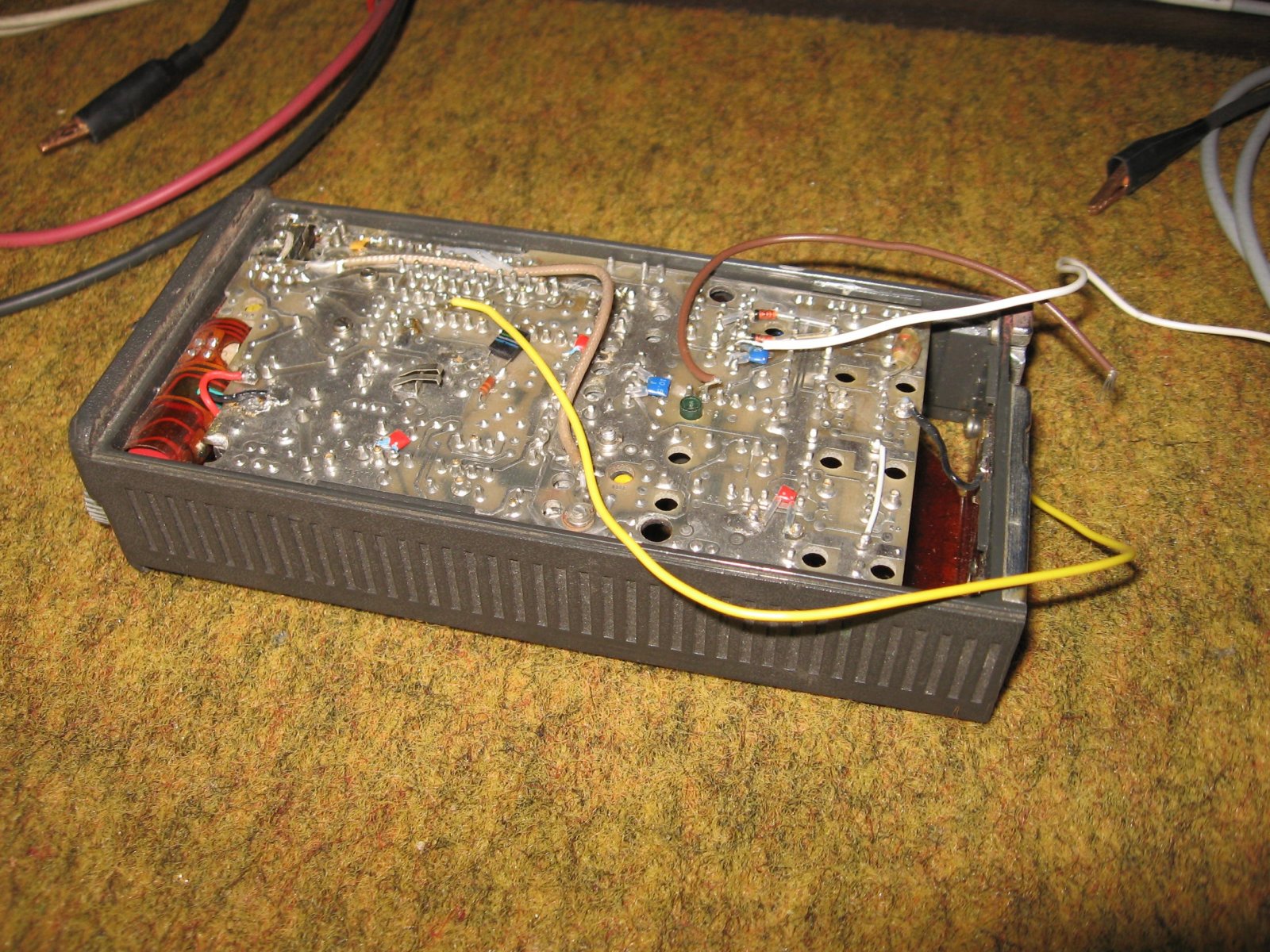
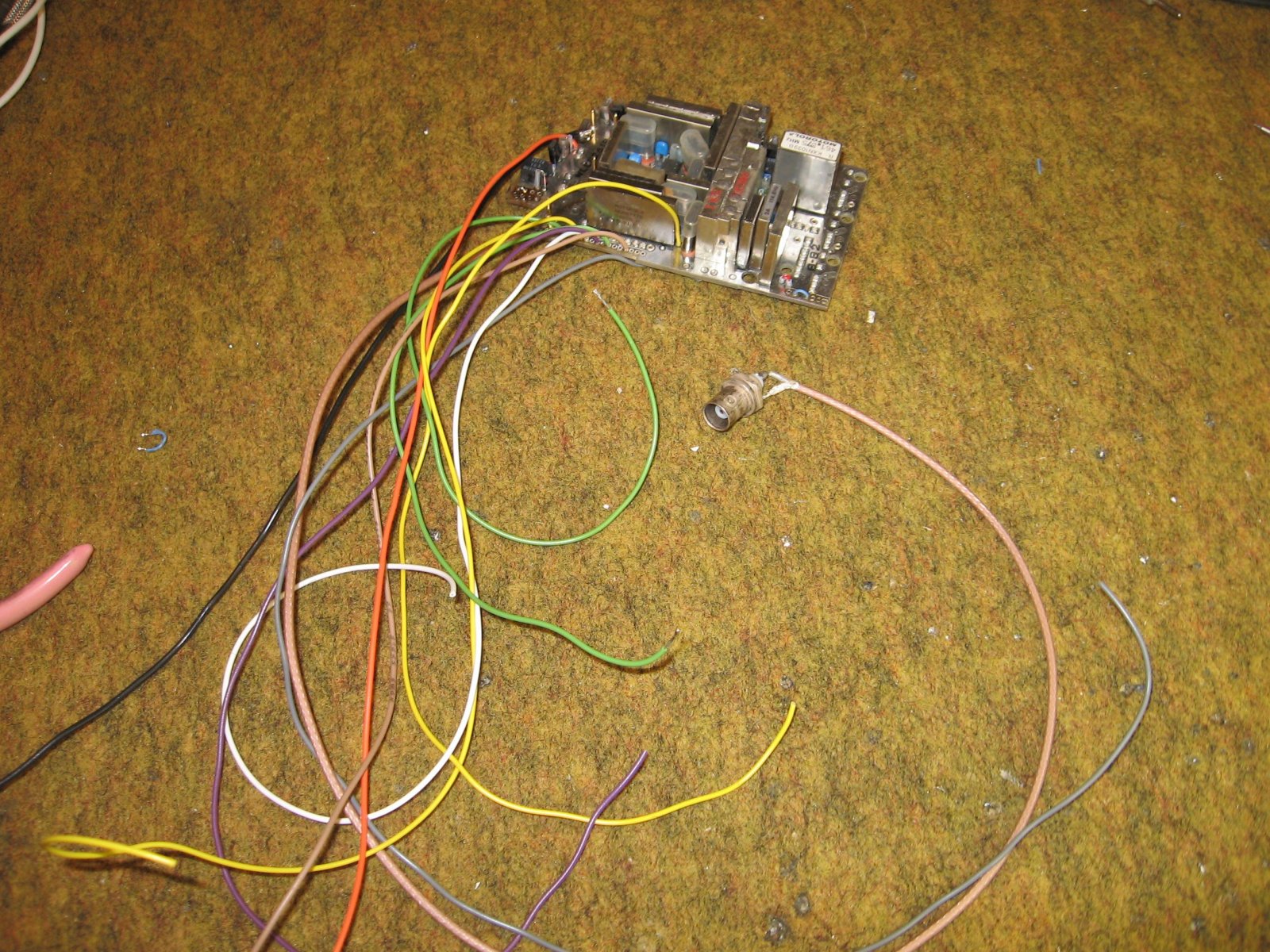
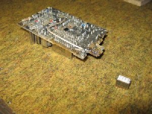
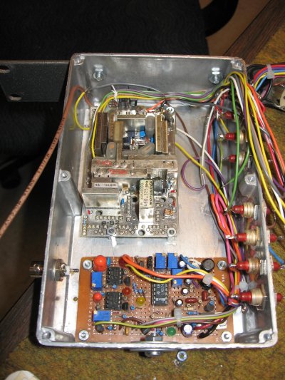
By taking the covers off you have the radio's main board in a (plastic) frame.
The extra wires you see were just used for testing/prototyping an earlier radio.
This receiver has excellent rejection. RF sensitivity into the box measures about -113 dbm for 20 DBq.
With an additional band pass cavity it should provide a good uplink at a mountain top site.
For the Omak project (only) the IDer is also mounted in the link box on the lid. ID audio runs into the cos/af board's aux input.
Its PTT line is paralleled with the COS/AF board's PTT-2 line. The COS/AF board provides the transmitter tail and time out.
The AF output drives the VHF (Micor) transmitter with a TLP of +3 dbm.
The project
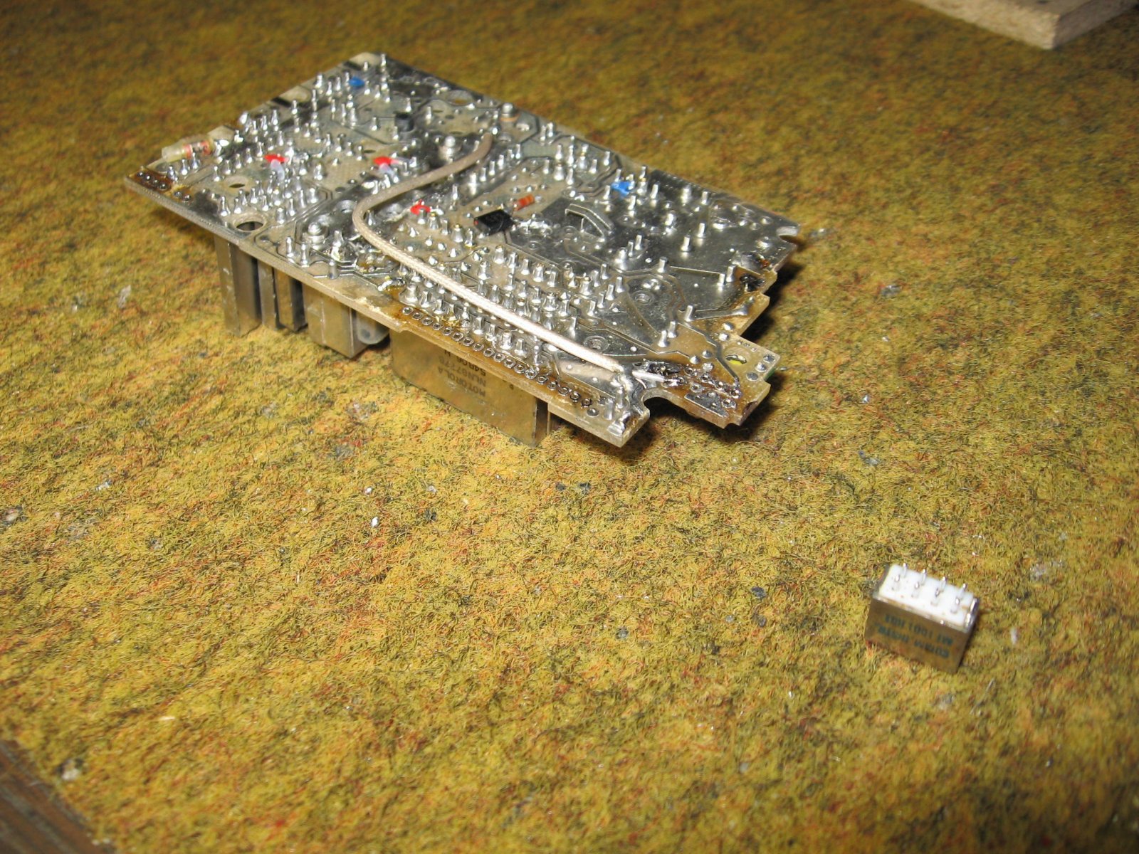
First, disassemble the radio, discarding the covers and side (rail) frame, and it's associated parts, such as the flex boards.
You'll end up with just the main board and all of its modules.
Depending on the type of link will determine what modules can be pulled as previously mentioned.
Remove the frame and you end up with just the main board.
For the Rx only you can remove most of the Tx modules, such as U101, 102, 103, 104, 105, 106, 107 and 108.
Put these modules away for a rainy day. Unsolder K101. You'll need to strap it, depending on link arrangement.
For receive only arrangement:
Install a jumper in the holes of either 6 or 7 to 8. This will enable the "R1" and "R2" (7.5v) for the receiver.
Install a jumper from 2 to 4.
This enables the outside pad to be the antenna port. Another alternative is skip this jumper and solder the coax directly on hole 4.
For SRG links, the latter was decided for simplicity.
Also, install a jumper from X2 to Y1 and CE5-7. This is voltage "F" (+4.6) for enabling either the transmitter or receiver channel elements.

Install wires for the radio I/O, per the list, at the end of this document.
Wire colors were chosen for association from previous repeater projects by the Author.
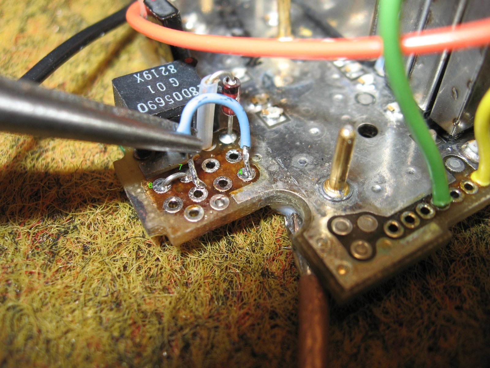
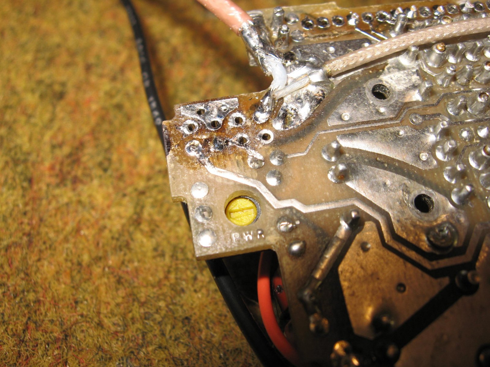
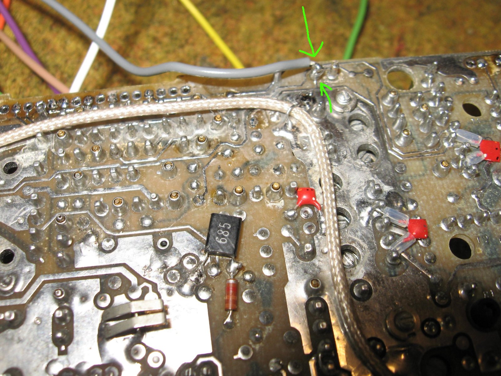
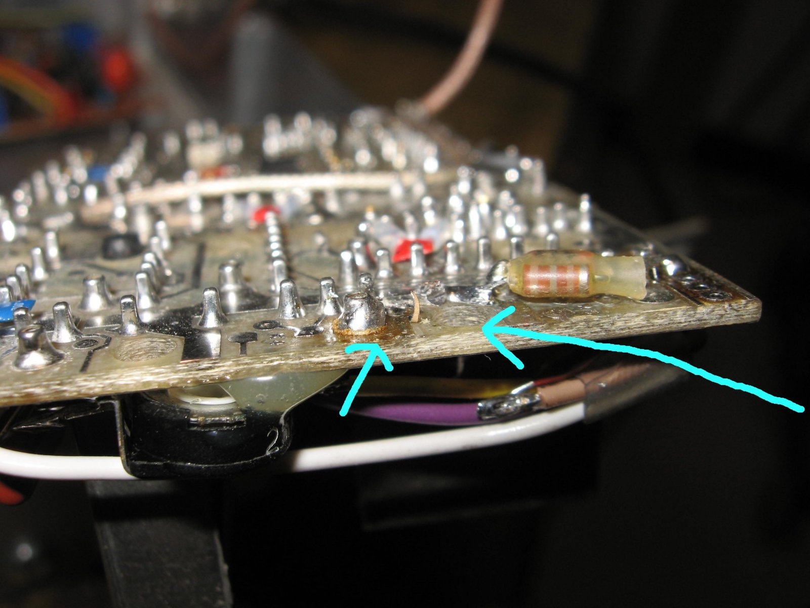
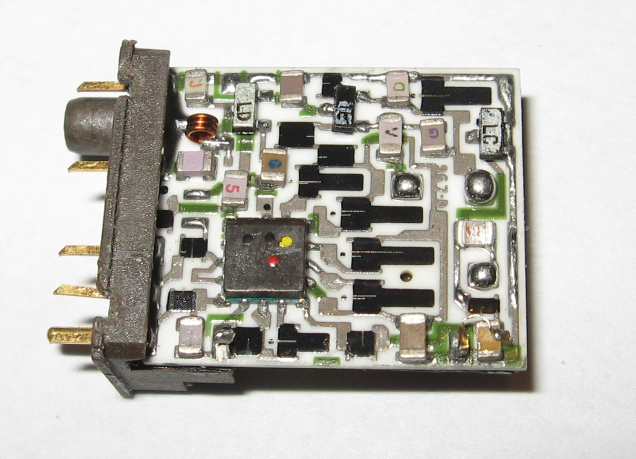
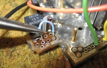
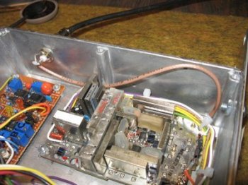
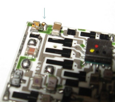
For the "PLI" (PL indicate) point, I-5 makes a good one (left picture).
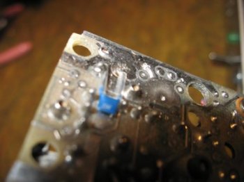
For a good connection for the "cos" is a hole, part of JU10 (towards U9 side, next to a crystal filter) (right picture).


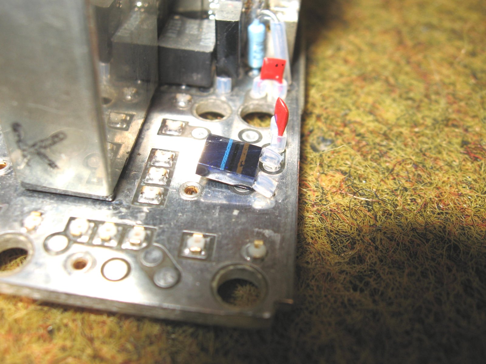
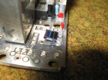
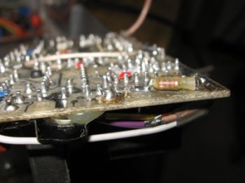
Sometimes little parts, such as this capacitor gets bent over. It doesn't hurt to leave it in that position.
One of the corners has a "post" that might conflict with that mounting screw.
You could shorten it up with some cutters, as that's not being used for any radio function.
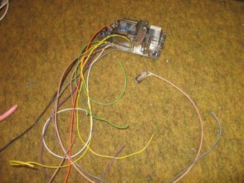
You can bench test the radio before finding a permanent box to mount it in.
Be aware you might have some RF issues with the squelch circuit, while out of a shielded box, with long wires, such as shown here.
Once it's inside the box and bonded, it should be quite stable.

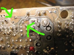
The left picture illustrates those two jumpers discussed; JU10 and JU8.
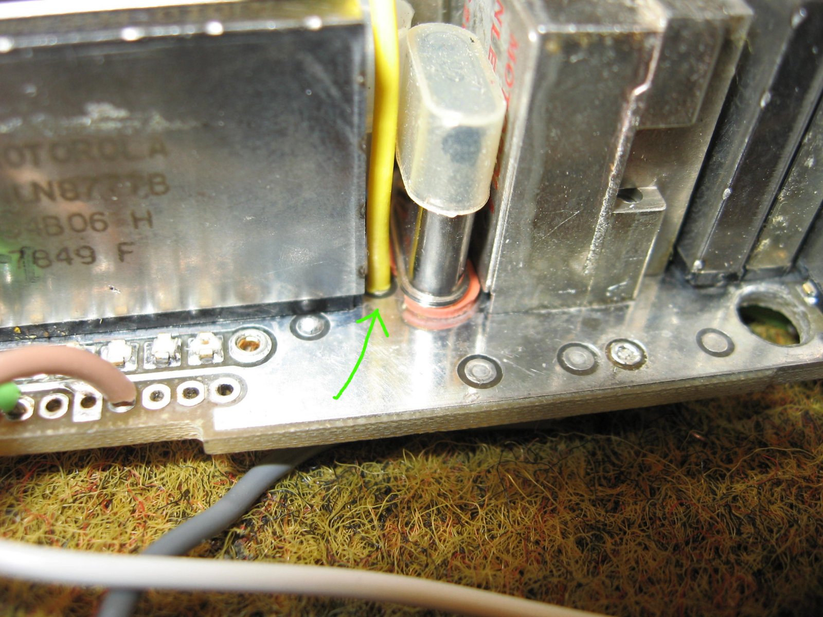
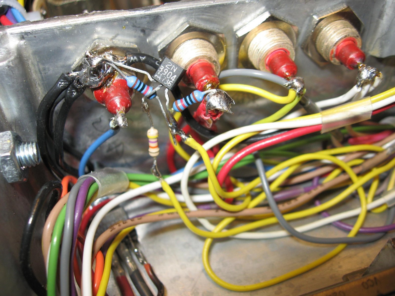
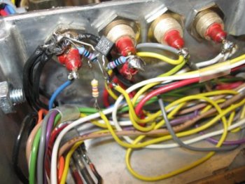
The right picture is just general wiring inside the RF tight box.
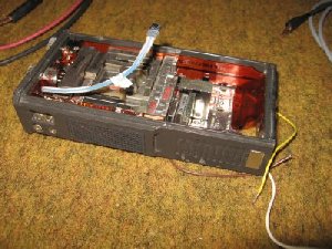
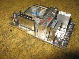
Here's how the board can be mounted in a shallow box, such as the Bud CU-247.
For this project was a "re-fit" for the prototype uplink package for "Omak" 20 Tx.
The wiring shown is in "rough" state, being this is a prototype in the working.
When you clean up the wiring, and perhaps using ties, making a "umbilical cord" leave enough length to allow easy flip out of the board for maintenance.
When you get the new crystal (element compensated) you can align the radio on the new frequency, perform the Rx frequency response and equalization
procedures as outlined in the AF/COS board (v5.4) project on this site.
On the left is the run you can lift to avoid shorting out the +4.6. line.
On the right shows rimming out the eyelet (+7.5 line) so the 4-40 nut does not short it out either.
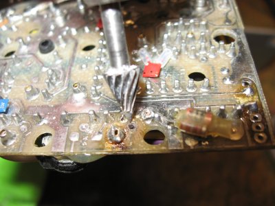
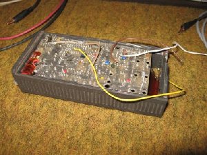
As additional short protection you can add an insulating washer on the one top hole. The right shows the main board, mounted in the box.
One the larger version picture (click on the thumbnail) an arrow shows the white washer, that's almost visible from this angle taken.

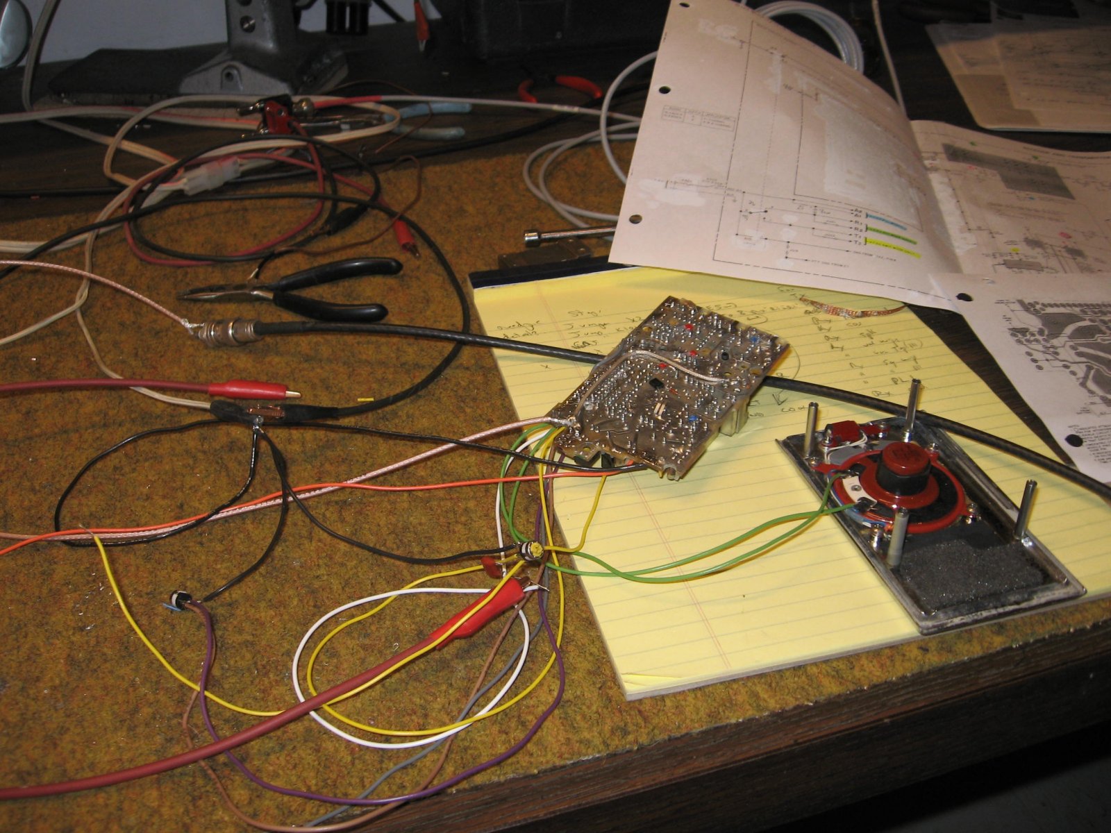
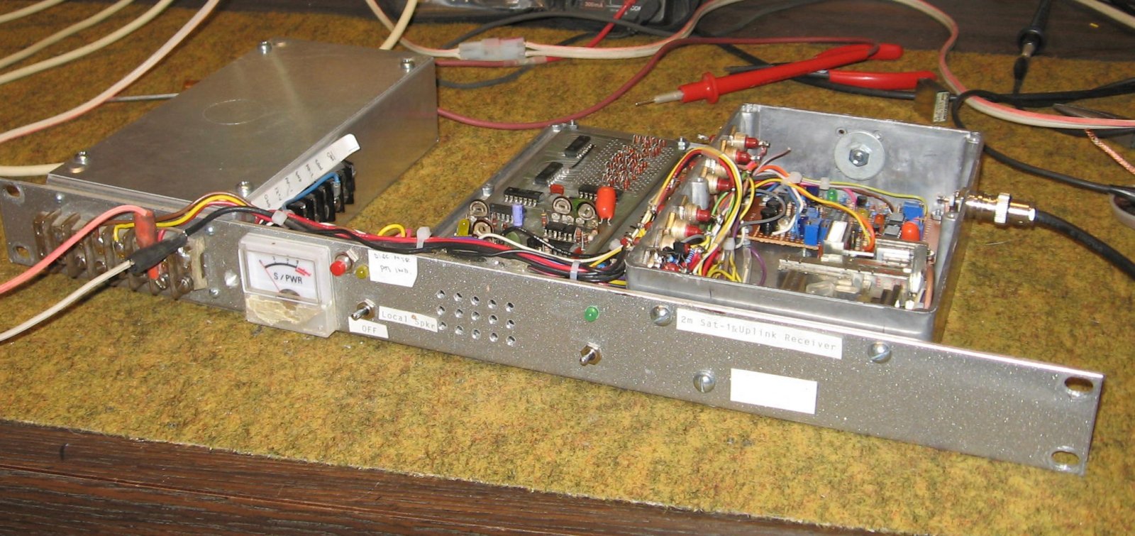
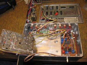
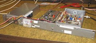
Here's the overall control unit for the site, being bench tested and aligned.
MX connection table:
|
Connection |
Wire color |
for: Tx or Rx |
Function |
Remarks |
X2-Y1-CE5-7 |
(any) |
Tx |
enable +4.6("F") to CEs |
|
K101-7-8 |
|
Rx |
enables "R1" "R2" voltage runs |
|
K101 2-4 |
|
Rx |
or connect ant. coax directly to 4 |
|
Cut JU10 |
|
Rx |
allows separate PL control |
|
Cut JU 8 |
|
Rx |
enables local audio CS |
|
| JU10 U9,U7 side |
YEL |
Rx |
Pickoff point for cos |
+4v sq; goes low on open |
E4 |
GRN |
Rx |
local speaker audio |
|
E12 |
GRN |
Rx |
local speaker audio |
|
E10 |
VIO |
Rx |
volume wiper |
|
E15 |
TAN |
Rx |
volume hi |
|
E7 |
YEL |
Rx |
squelch wiper |
|
E8 |
WHT |
Rx |
squelch hi |
also discrim. TLP -7dbm |
I5 |
SLT |
Rx |
PL indicator |
|
|
|
|
|
|
Note: As of 2017 most or all of the crystal vendors stop performing frequency compensation as a service. Therefore, you may have to do it yourself.
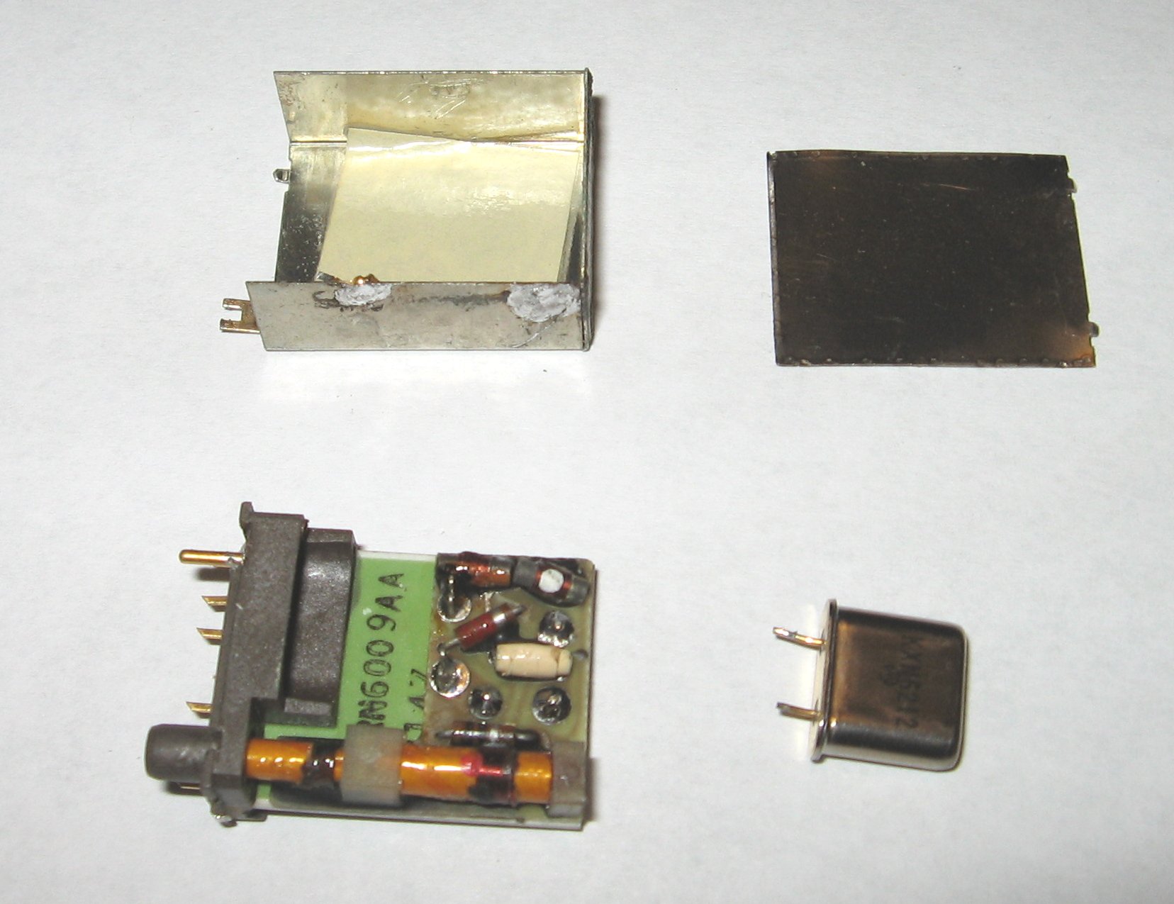
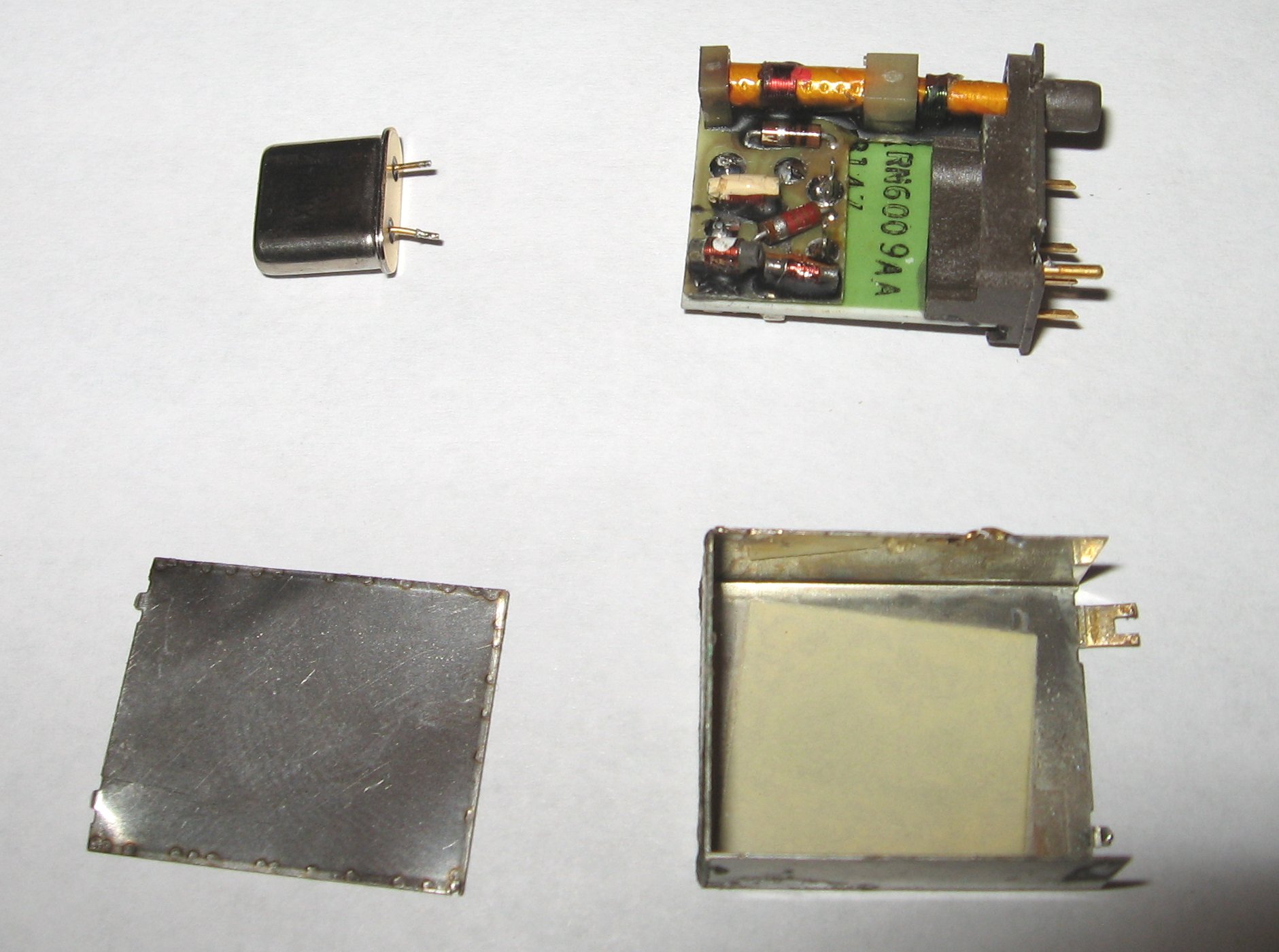
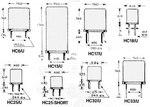
For the UHF MX-350 radio receiver is operating frequency minus the IF of 21.4 MHz divide by 6 = the crystal frequency. Also, the crystal should be in series resonant +- 10PPM 0-70C with third overtone mode, in a HC-18 holder (AKA HC-49/U) being the small type. Here's a chart for most of them.
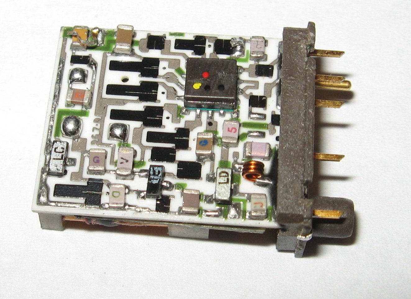
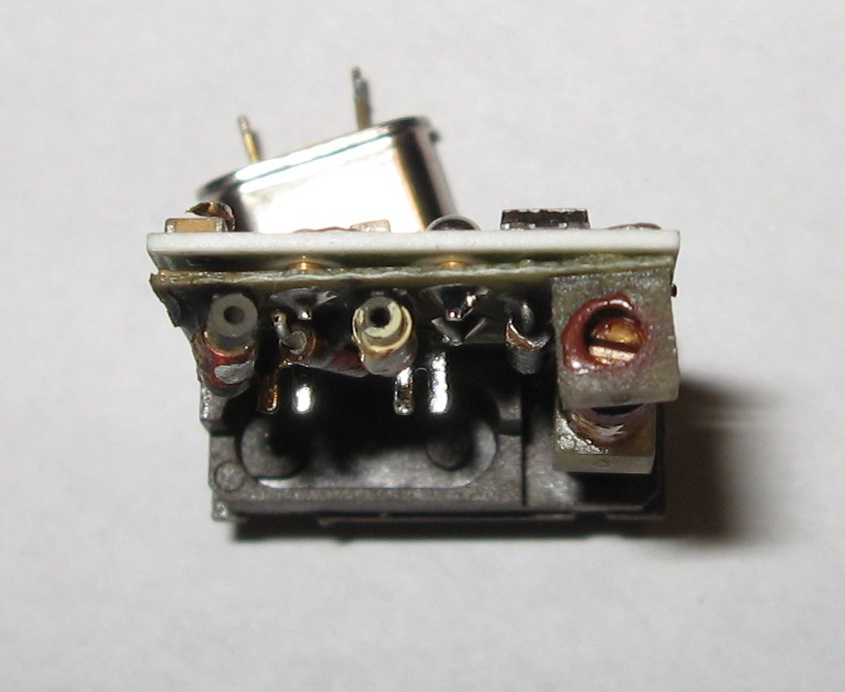
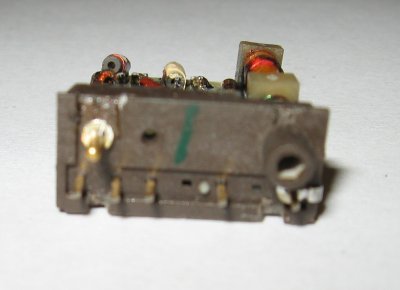
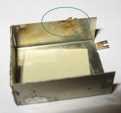
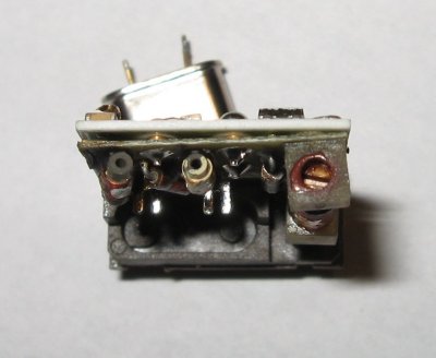
Here's some pictures that may help you. Disassembly of the channel for the MX radio is "tricky" at best. Note the two tiny ground straps on the PCB.
Fortunately, the case can be soldered (spot weld is not necessary).


Additional notes:
The volume coupling capacitor, C304 0.0047 uf, was substituted with 0.0068.
Also, the Squelch C301 called for a 0.27uf, and a 0.22 was substituted.
This was mainly due to a lack of stock, during re-fit of the unit in 2006.
Both changes did not seem to affect the receiver's performance.
Later version will have the specified capacitor values in them as parts are available.
Even though the squelch control (pot on the main board) can be left at threshold (around 10 dbq) it's set to near maximum for site
IM protection.
At F.S. the squelch now operates at 20 dbq, which just happens to be the rated sensitivity, which was measured to be around -113 dbm, at the
original frequency the channel element came in on the range of 460 MHz.
At a later date "M2" could be used as an AGC line to drive a meter circuit for front panel viewing of present/calculated R.S.L.
Presently, the meter and push button can be used for netting the receiver.
Drawings
Most of the drawings are in PDF format
Diagram For the "stock" radio
Board layout Mx portable radio
Transmitter downlinks - Block and Level For the downlink transmitter arrangement
Receiver uplinks - Block and Level For the uplink receiver arrangement
This may be copied in complete form only for non-profit purposes, such as for the knowledge for the amateur radio service, with the Author credited
as designer. For other arrangements please contact the Author.
Copy write: AK2O 2007
![[SRG home Direction]](images/srghome.gif)