The FM transmitter Modifications
After the trimmers are sucked out, perform the jumpers for both the FM and A+ switch
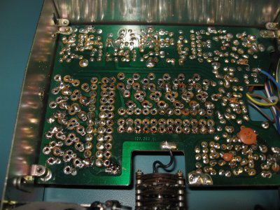
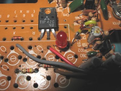
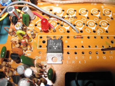
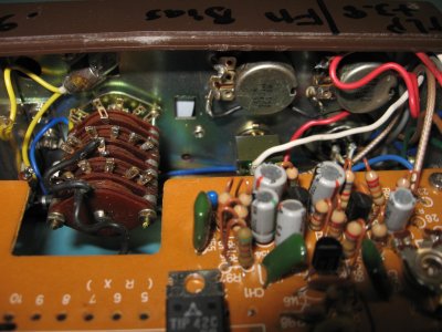
Here's an overall view of the modifications. Remember there are several prototypes over the years, therefore it's possible the picture shows different physical locations of some parts.
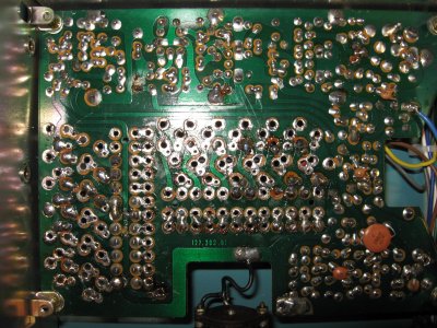
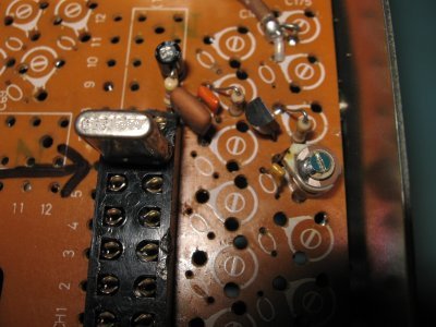
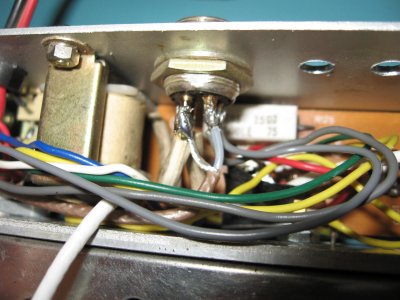
With some close ups of the modulator and T-R relay bypassing. Not visible is the RF jumper in place of the rely contact
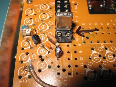
Detail of the switch
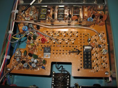
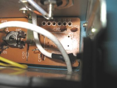
Reduction in misc wiring
The front and back. This chassis was from another (rough) project from the left-over holes in the back.
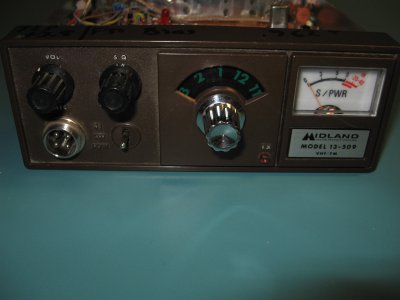
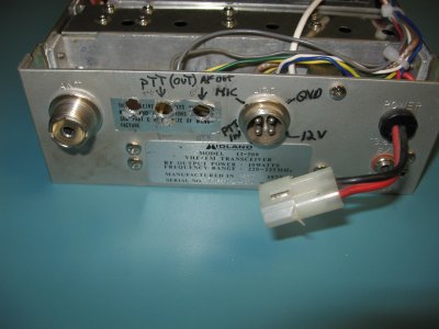
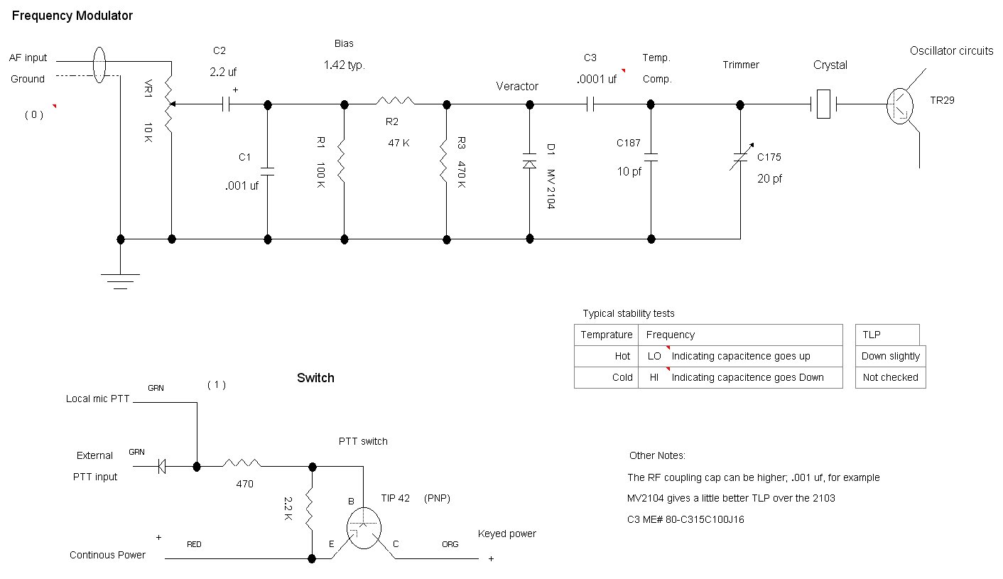
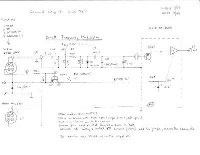
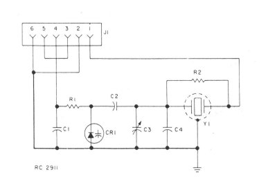
Diagram of the F.M. Circuit. Typical bias is .8 v +. This allows the veractor to "swing" at the audio rate in a linear fashion. On the right is a commercial version designed by G.E. in the 1970's. This is called an "ICOM" which is a complete plug-in module. For the GE used PM however, the temp comp circuit is FM, but not used for audio. There's another document to change that on SRG's web site. Below is a better quality image on the FM circuit, inspired by a comment from Groups IO.
This may be copied in complete form only for non-profit purposes, such as for the knowledge for the amateur radio service, with AK2O credited as designer. For other arrangements please contact the author.
Copy write: AK2O 2007
![[SRG home Direction]](images/srghome.gif)