Introduction
Antennas are an extremely important part of a radio station. They provide performance to radiate R.F. out to distance receiving stations. The more elements (in the proper phase) results with more E.R.P. ( Effective Radiated Power). Antennas are subject to environmental wear, from heat, cold, sunlight (UV) vibration, wind and ice loading (not even covering the man-made problems such as bullets, etc.) The type of antenna we will be covering is an omni-directional, gain type. This type is used for base station and repeater service, even on remote and hostile mountain top sites.
Requirements
The electrical part needs to be protected with an outer "shell". The outer part can be plastic (ABS) or fiber glass, both which have little effect on the ERP or return loss (RL). The base of the fiber glass can be pushed into a "base" mounting pipe, normally made of aluminum #40 pipe about 2 21/2 inches in outside diameter and 2-3 feet in length. The bottom of the antenna either has a RF connector or a "pigtail" coming out, terminated with the connector. The connector comes in either UHF-male (PL-259), DIN or type "N" male or female. The latter two are better connectors.
Sources
Several commercial companies manufacture this type of antenna, such as Phelphs-Doge (now Celwave), db-Products. Telewave and Sinclair, to mention a few. To buy them new, commercially is very expensive; in the $1,000-$2,000 range when you consider shipping. Phelphs-Dodge made a base station/ repeater antenna called the "Station Master". I consists of several end feed half wave elements, mounted inside a ruggidized housing made of fiber glass. It held up fairly well for remote mountain top sites, even hostile ones with winter ice loading.Theory on the Station Master
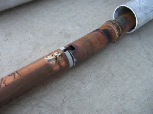
The electrical part of the Station Master antenna has a serious flaw in the design. The matching area involved 1/4 wavelength parts therefore, RF currents where very high (half waves have high voltage, etc.) Because of the high RF currents any station trying to duplex develops a problem after some time. A duplex station's receiver is trying to hear a weak signal about -100 dbm, while transmitting a +50 dbm on a another frequency, close by. In the case of amateur repeaters, the 2-meter band plan is 600 KHz split between Tx-Rx. Normally a well made duplexer will isolate the Tx noise and desense from the Rx, making a clean repeater. The matching stub for the Station Master is made up of three dissimilar metals. Yup, you read right; they use an aluminum pipe for mounting the base. The matching stub has a pressure seated ring inside of brass. The brass presses against the inside of the aluminum base and the copper matching section. In time galvanic corrosion makes a bad electrical connection. You may see this when taking the antenna apart; some while corrosion around these connections. The (now bad) connection makes "noise". This happens from the station's transmitter's energy causing the noise, here. This will desense the station's receiver. It's mostly noticed on weak user (input) signals. When the wind blows and wiggles the antenna, making and breaking this connection, the signal will have a static or click-click sound to it. If this condition goes without action the desense gets bad enough to disable most of the repeater's range.
Free source for amateur Service
In commercial service the customer will call a service shop with the complaint of noise and/or poor range, getting into the repeater. This bad connection generally does not have a big affect the power out; only receive sensitivity (input). The repair shop checks out the problem to find a bad, noisy antenna, and calls for a replacement. This replacement is expensive and discarding the old, bad antenna adds to that. Sometimes old antennas are left on remote sites and sometimes end up in a shop's attic for years or ends up in the dumpster, all cut up. Amateurs can pick up bad antennas, to both parties advantage, usually free to whoever wants them. Any sensible shop will mention to the amateur this is to never go back in commercial service.Restoration-Repairing
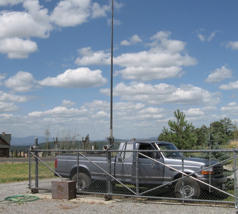
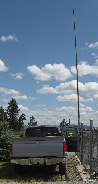
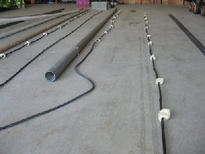
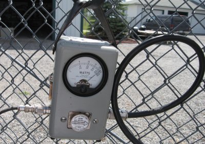
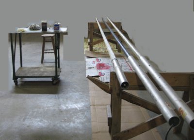
Bringing these bad antennas home presents some possibilities. For one, can "repair" the existing antenna insides, by cleaning up the corroded matching area. Soldiering the brass ring to the copper stub helps a lot. Another option is to strip out the insides to discard it and install a new home-brew collinear antenna, made out of coax section as. The A.R.R.L. repeater handbook has a good design for such an antenna. There is also a page (on this site) about this idea.For the "test" the Author mounts the antenna to a fence post while using the vehicle for a power and RF transmitter source and a general "table" to lay out the equipment for this procedure. The metal fence can actually help make a ground plan with signal tests later. The meter can be nicely hung on the fence as well.

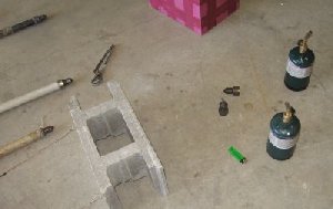
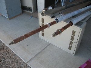
If you determine the antenna is bad, dissemble it. Starting with the correct tools, you'll need a couple of torches, the right size allen wrenches, for the 3 screws on the side and the 2 up, inside the pipe. The right picture shows completed home-brew antenna replacements standing by for install.
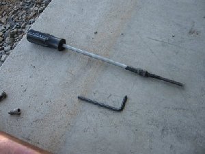
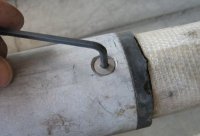
Start with removing the 3 side screws holding the top of the matching section (inside).
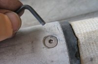
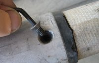
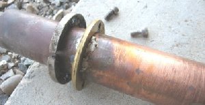
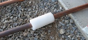
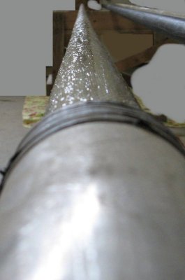
Next up, inside are 2 allen cap screws. These hold some rings that press against the inside of the aluminum pipe. It's not necessary to completely unscrew these; only loosen. Then using two torches (for quicker heat) warm up the top, tip, being careful on the fiber glass area. In a minute or so you can grasp the (brass) top with some large pliers and pull it off. The right picture show a difference version of antenna which does not require unsoldering; just removing an allen head screw.
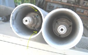
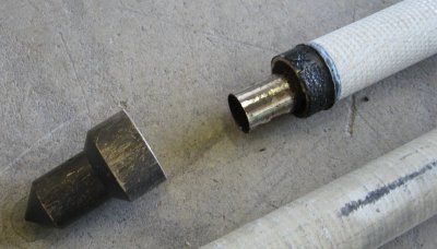
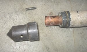
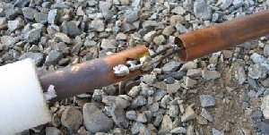
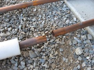
Now that the inside antenna assy is free you should be able to pull the entire part out of the bottom. You might have to jerk the matching section a little out as it sometimes hangs up on the inside of the pipe. You can study the matching section and how it feeds the rest of the radiating elements, above it. Clean up the corroded section, rings and such. For a good electrical connection you can solder the brass ring to the copper matching section. Solder only one or two spots, so it still can flex and bend when the screws are tighten on the assembly.
You might also want to inspect each element for solder breakage.
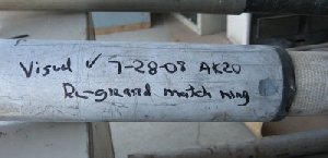
When you've completed the reassembly use some RTV to seal the top and those 3 screws around the outside of the pipe. Check the antenna for return loss and document what you've found, for future reference. For those math challenged folks a RL of 10 db a power ratio of 1:10, so if your watt meter shows 100 watts forward that would be 10 watts reflected; no so good but usable. A RL of 20 db would be great, being the power ratio of 1:100, so if your watt meter shows 100 watts forward that would be 1 watt reflected; certainly a good match.
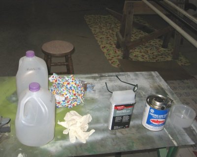
Another issue for the fiberglass type of antenna, in time, the housing will start to get "fuzzy" from the glass coming through. You can repair that as well. Some boat dealers carry fiberglass resin along with some NAPA stores, especially the paint supply ones. Verify they are selling you the proper catalysis for that type of resin.
Set up a table for the items you'll need for this task as shown in the left image. This would include the resin, catalyst, some rags, gloves, etc. Milk cartons make a nice disposable dish; cut and use the lower 1/3. The center image is all the antennas laid on sawhorses. Install a long deck screw on each side of the antenna to keep it from rolling. When the resin is applied it should have a glossy look while its drying as shown in the right image. Put cardboard or (disposable) painting tarps down to protect the floor. The resin is not the most fun thing to clean up.
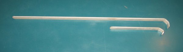
One last item; many times the ground radials are broken. You can make new ones out of aluminum strips. Showe here are 2 bands 2-meters and 70-cm. The former is 721mm in lenght, 16mm wide and 3mm thick. The latter is 184mm in lenght, 16mm wide and 3mm thick. If you are metric challanged the figures are 20 5/8", 5/8", 1/8", 7 1/2", 5/8" and 1/8" respectivily.
![[SRG home Direction]](images/srghome.gif)