Cavity notes

Introduction

Amateur communications can use point to point in a simplex RF path. Some have some limitations depending on the frequency band(s) used. For lower HF is dependent mostly on ground waves while middle HF is dependent on the F2 layer (skip path) in the upper atmosphere. VHF and UHF is dependent on a line-of-sight path. Simplex communications is on one frequency. Because of line of sight the signals are blocked by obstacles such as buildings and hills. Mobile and portable (hand-held) increases this limitation. A station in a high location can get around most of this limitation. However it's impractical to be a this high location, not moving for a long time especially under winter conditions. Therefore, a remotely operation station in the form of a "repeater" is the solution and a great improvement for RF coverage over low-level simplex work.

A Repeater normally operates on two frequencies; the user goes in on one, while the repeater retransmit's the user's signal on another. The other users enjoy increase coverage and is especially valuable during a conversation among several users, whether operation in base, mobile or portable methods. This repeater normally receives and transmits at the same (high) location. In order to do this there has to be RF isolation between it's receiver and transmitter frequencies.

Some repeaters operate a separate antenna (and feed line) for each receiver and transmitter. However, the cost and labor is high because of these two components. Most repeaters operated on a single antenna (and feed line) for the advantage of lower cost but with other considerations. The isolations requirements are high over using separate antennas for the repeater.

A word about RF management:

RF management in the form of "cavities" is needed and generally required from the site owner for protection on yours and your "neighbors" equipment. It's safe to mention many sites do not actively require or enforce site standards therefore, one can "get away" without filtering. However, this is generally a bad practice and can have damaging effects on the reputation of that repeater owner or even the general amateur community. Another classic example is one installs a "packet" station (or APRS) which normally is a plan, simple mobile radio with no filtering. Fortunately, most of these packet radios operate in simplex mode therefore, external (cavity) pass-filtering is a simple task, in most cases.

There are a few exceptions to this advice; for example, if you are the only station at the site with no nearby stations to electrically interact with yours may be acceptable. In addition, if the site owner is not concerned about protection you are on your own. But this could have negative affects in the future. Just remember in the future; if there is an RFI problem in the area and you are found to be the cause you will have to be the first to take action to correct it and possibly the first to blame in any future problems. It's expensive for an affected customer to pay for a commercial radio shop to find the root cause of interference which could lead up to several hundred dollars. To make matters worse this effort by the shop won't be noticed until it's too late to save your reputation. In some cases the offended station and person will be upset and maybe even hostile; discovering you did nothing for site (filtering) protection. Therefore, as a pro-active plan, a pass cavity is the bare minimum one can install on a transmitter at a populated remote site.

A cavity is an RF resonant device for filtering certain frequencies either passing them, rejecting them or both. It can be made for three modes; pass, reject or a combination of both. We'll cover the differences but let's first go over the cavity itself. A cavity has basic components:

  • The outside; being the cavity; a cylinder or "box" made of conductive metal; aluminum, copper, etc

  • The inside resonate "stub", being a fixed length tube mounted only to the top inside of the cavity,

  • The inside piston, being movable and a electrical part of the stub,

  • A coupling loop (or 2) to transfer the RF energy from and to the coaxial transmission line,

  • Other tuning devices as part of the cavity's RF characteristics.

    To measure a cavity's frequency response a signal is injected into the cavity's "port" which is an RF connector for a coaxial cable to connect. A second cable is connected to it's output and placed into a spectrum analyzer or other RF detection test equipment. The signal is moved in frequency to result in a level response output to be display on the analyzer.

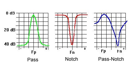
    Shown here are some level plots with the X-Y axis displaying frequency verses level, respectively. Front the left is a cavity in the pass "mode", then reject, on the right is a combination of the previous two modes in a pass-reject mode. Each has specific applications for RF management either for normal repeater operation or to control RF interference or both. As mentioned earlier a pass cavity is a good general practice at a populated site.


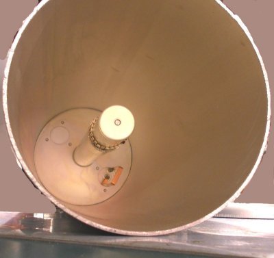
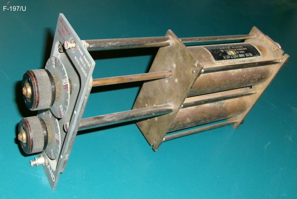
    Shown here is the inside of the cavity in the reject mode. This image was showing a band conversion (another article) but will illustrate the points. As you can see the piston can move up and down inside the stub depending on the frequency you wish to work with. Notice the "finger stock" that provides a positive electrical connection between the two parts. This cavity is in the notch mode therefore, only uses one coupling loop. The distance between the coupling loop to the stub affects the "Q" of the cavity circuit. Most commercial cavities have a scale label affixed to the outside top so one can "dial" in how much loss (in log) is desired. The higher "Q" (quality) of this circuit increases the filter plot but with the cost of more RF insertion loss. Therefore, it's a balance between the two for effective RF management of a repeater sight.


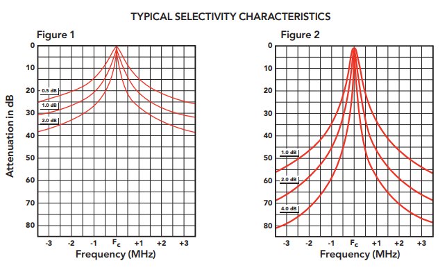
    This is a level plot for a cavity in the pass mode. The different lines (plot) show the response for different coupling loop settings. As previously mentioned it's a balance. A better circuit Q protects outside frequencies better but at the cost of most RF insertion loss on your station.


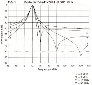
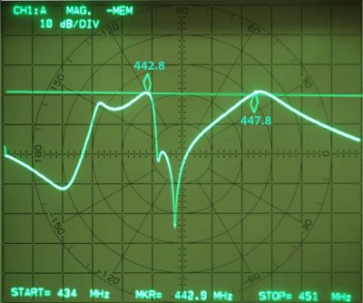
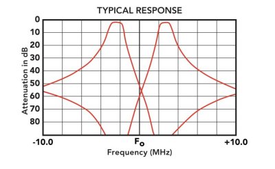
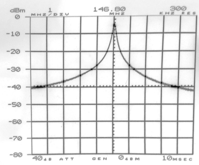
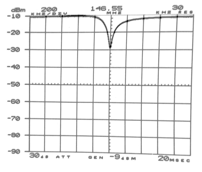
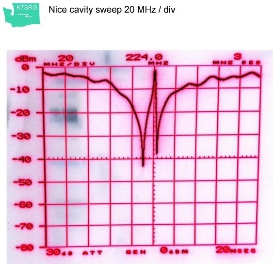
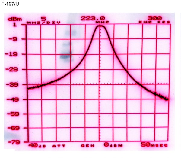
    Here's some actual plots for a cavity in the notch mode


    p> 


    The duplexer

    So far we've only discussed cavities. If you connect several cavities together makes up a duplexer (singular term). A duplexer will permit a repeater station to receive and transmit on separate frequencies, on the same antenna (and feed line) at the same time. It's primary purpose is to protect the station's receiver. The secondary purpose is to protect other nearby stations.

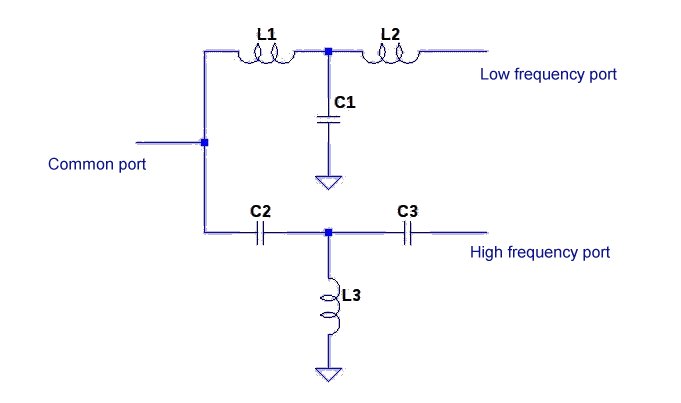
    Let's look at several plots for various brands/type of the duplexer. To start with here's the electrical equivalent of a duplexer courtesy of VK1SV. Because of reactive circuits you can imagine cable lengths are important. Coax cable electrical length is affected by "K", being the velocity constant. RF travels in free space at the speed of light. However in cables is "slower" therefore, electrical length has to be calculated and cut when interconnecting cavities. It's also a good rule to be aware of when connecting to external equipment, such as the repeater's receiver and transmitter. In addition, there's other filtering devices such as an RF isolator (circulator), however is beyond the scope of this discussion, presently.


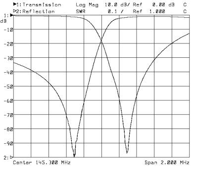
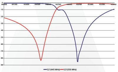
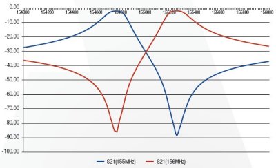
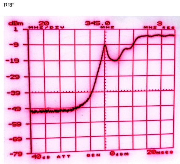
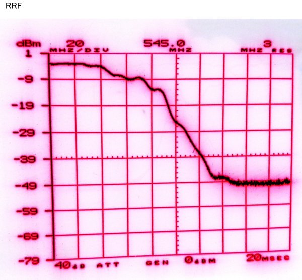
    Here's some plots by various brands of commercially made ones in the band reject mode.


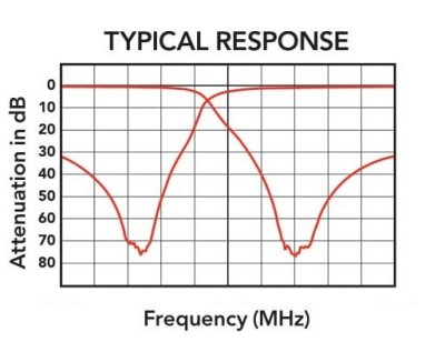
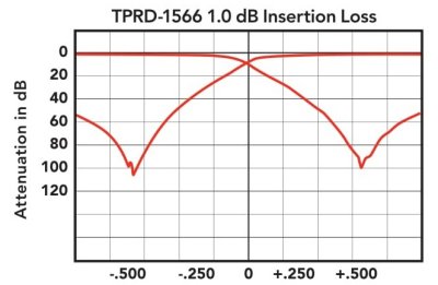
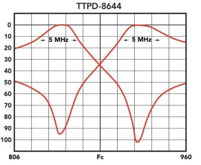
    These are in the band pass-reject mode:


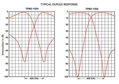
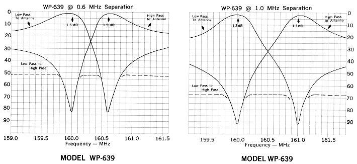
    Here's a familiar brand and type of duplexer used in the amateur community; the Wacom brand. This shows you can use this model either in close spaced (600 KHz), as with most 2-meter repeaters or a wide spaced application in a non-standard split. Another use for a duplexer can be used in the "diplexer" mode, using two transmitters only as a combiner. This has an advantage of two transmitters sharing a single antenna for the obvious advantage of lower antenna and line cost.


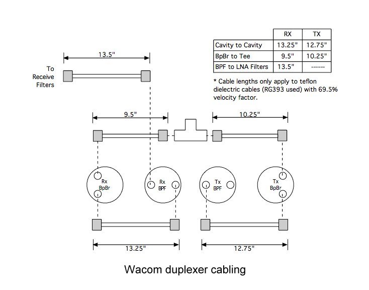
    Here's a nice guideline to confirm the previously mention cable lengths are important:


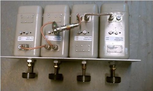
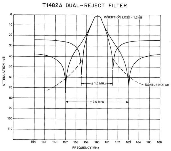
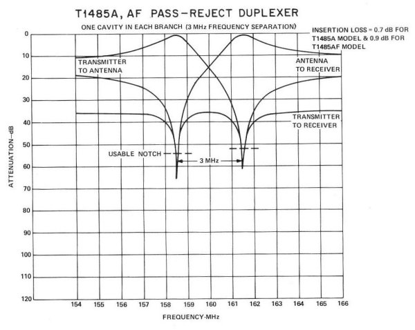
    Here's the "square" type of duplexer that Motorola made 1960's ~ 1980's. They can be configured for two or a four-cavity duplexer. For the T1400 series on VHF they can be 1 or up to 6 MHz separation. Even though most of these splits are for commercial this may give you some ideas for amateur use. These plots show the spec of what of the seven arraignments do.


    Telewave makes a vari-Q series. The main tuning piston is locked with an allen type set screw. Use a 5/32" (0.156") to loosen prior to making an adjustment.


    For a general site filtering to manage AIM the Author tried out a couple of brands for the spring of 2023.

    These three are the Sti-Co band. They make a solid built fitter. Inside here shows the well-built unit. There is some "oil" around the edges between chassis and top lid. It's assumed it's there for metal interface therefore, was left alone.


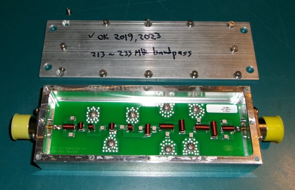
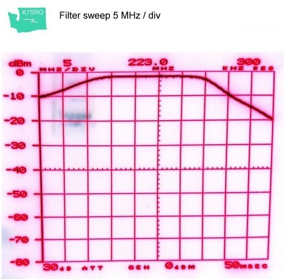
    The sweep showed good coverage for the amateur 1.25 band. It's strange since their web site talks about below the amateur band. It's possible years ago when the Author pick this up he retuned it, possibly by closing the coil distances, etc.


    And here's the Tx-Rx brand which has far more control in the narrow portion of concern.


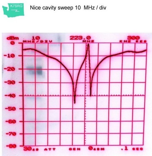
    It's obvious the latter brand is much more suitable for close spacing interference (AIM) control.


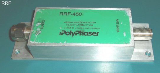
    Here's a couple more filters. The first one is by Polyphaser; the second is MIL surplus, dual cavity fiter.


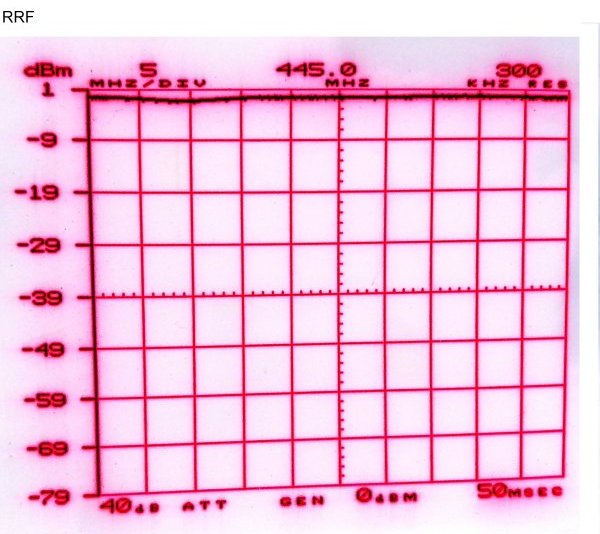
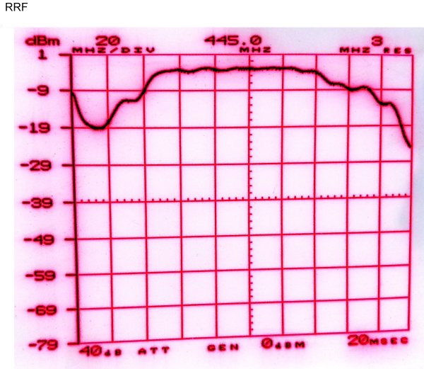
    Here's what the sweeps-plot look like.


    This one is miitary surplus and real nice tuning. However, there's no know lock to prevent them being bumped and changing the tuning.


    [SRG home Direction]