Closed space Dipole for 1 1/4 Meters

A simple dipole (unity gain) has one advantage of a small footprint. This is important on a mounting structure, such as a tower, where there is a limited amount of room to mount antennas. In the case of remote mountain top sites, this also has an advantage of lower wind and ice loading in the winter. Since mountain tops can have harsh conditions in the winter, any antennas expected to survive for several years either needs to be built with heavy duty materials or protect them in some sort of an enclosure. The latter is being discussed there.

ABS (black plastic) sewer pipe is fairly strong and if the surfaces are kept small it will usually hold up for several years at most sites, except for the extreme ones. For most sites linking is done on either one of the VHF or UHF bands. If unity gain (none) is acceptable we will cover them for the 1 1/4 meter band.

This version is significantly stronger than the other version. This accomplish two ways; the distance from the mount to the radiator is cut in half, thus reducing the ice loading. The other is additional cross pipe supports; three of them as compared to just one on the other version. Being close spaced there will be some cases this causes RF pattern distortion. This can be dealt with for link purpose, while moving the antenna around some while the far end observes the link's RSL for maximum. Also if mounting to a wood structure, such as the side of a building or pole this distortion probably will not occur.

For this version cut a 10-foot stick of 1 1/2" ABS pipe to several pieces and use the following fittings as well.

  • Four 12" pieces
  • Three 6" pieces
  • Three "Tees"
  • Three 90* vent
  • One 2-foot piece of 1/8" welding rod.

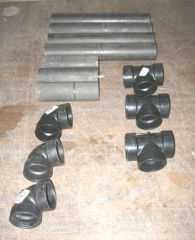
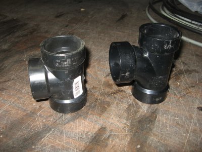
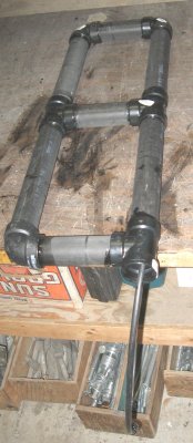
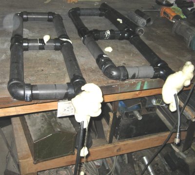
    A word about the Tee fitting. The 'straight" Tee shown in the middle picture, left side is real nice for this project. However most stores only carry the type on the right side. The latter will work but be sure to orientation all of them in the same direction so the frame work comes out straight. Also, the latter fitting is less cost. If this is your first antenna you may consider laying all the parts out to get oriented on assembly. You get one chance to get it right, with the glue setting up in 10 seconds after application.


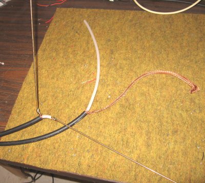
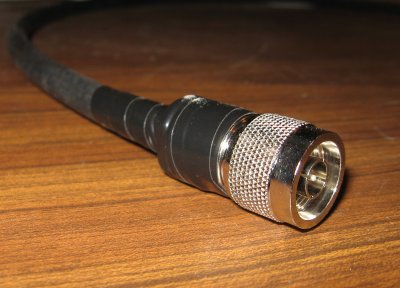
    For the electrical part cut a piece of coax 4-foot. One end strip back 2". Cut the rod in two; for two 12" pieces. Solder each rod the coax's center radiator and the other to the shield (return). An alternative way is not to use any rods. In this case make the coax 1 foot less. Strip the coax back 13" to make up a set of 12" elements. You'll be pulling the center out of the braid. Tricky task, but do able. Then terminate the other end with the appropriate connector. The finished product will make a 24" pigtail. If this is too long make your adjustment as needed. SRG installations call for an N-male for antenna "pig tails". 24" is a good overall length to work with on the tower installation, taping, sealing under most weather conditions.


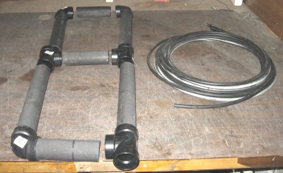
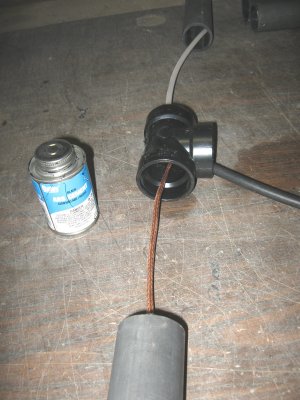
    The other version instructed to assemble all the pipe first, then "fish" the coax inside. While this works, ok, here's an alternate way; Starting with the feed point, slit the pipe and its fittings around the coax. Then glue all of them in place. You'll get some glue on the coax, however should have no impact on performance.


    You can foam the inside now or later with expanding foam (insulation) that comes in a spray can at most hardward stores. Drill a hole just big enough for the nozzle to fit in. A normal spray can will do two antennas nicely. The excess will push out to the bottom. Just leave it to dry, normally overnight. The hardened foam is far easier to clean up (and cut-out) over the guey, sticky mess. Foaming will nicely secure everything inside against vibration (boucing in a truck to the site, etc.) and seal the bottom from bugs, etc.


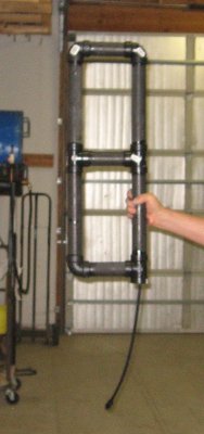
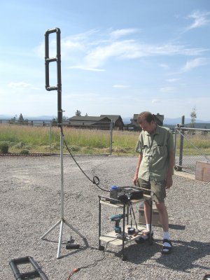
    Now you can check the return loss, either with a thru-line watt meter, or better yet, antenna analyzer. If you suspect "RF spill-over" (lack of decoupling) try a couple loops in the line as a "choke".


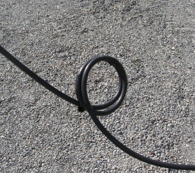
    Here's a couple sample sweeps, one without the choke and one with.


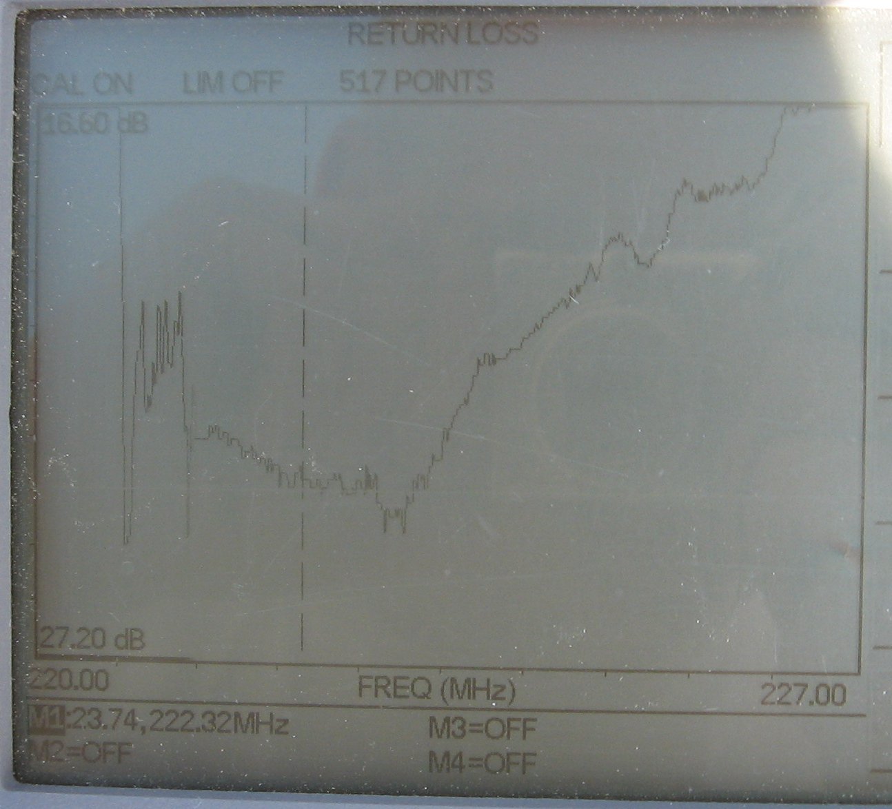
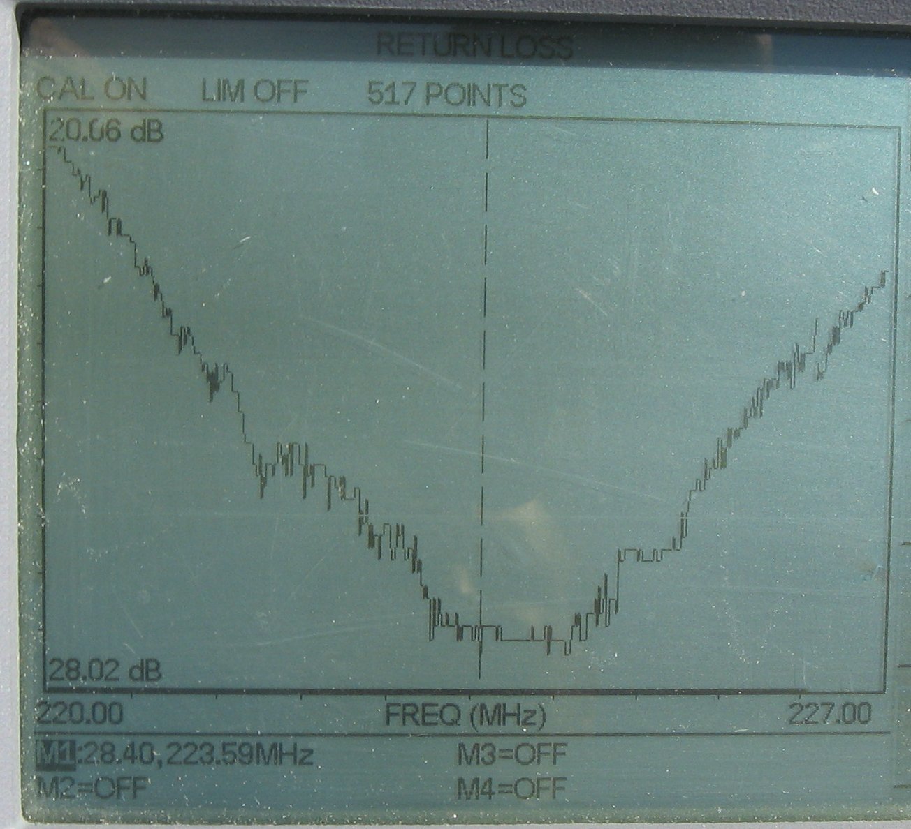
    A "chart" version is availible. Note the choke affects the resonant frequency:

  • #10 built

  • #10 built with a coax choke

    For install on the site, hose clamps work great for mounting the antenna on a "V" type surface, such as "U" channel or "L" angle metal. See some of the other bracket projects for ideas like this. Last thing you might wish to test the return loss (VSWR) either hand held or mounted on the tower. The reason the pipe is all 12" is the wavelength, plus the distance from a side-mount tower arrangement will be 1/4 wave length for this band. If you wish other patterns adjust the one pipe's length between the Tee common and the 90* fitting, as the other version instructs.


    [SRG home Direction]