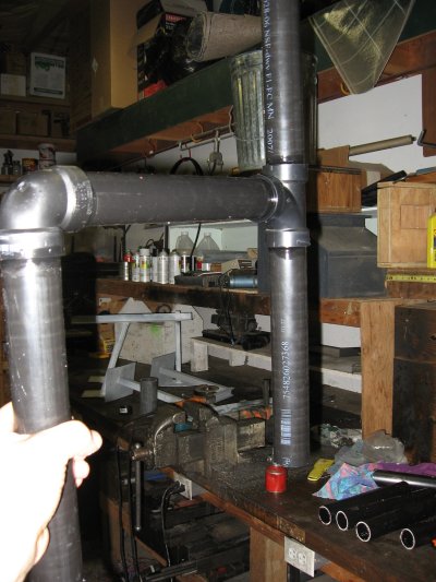
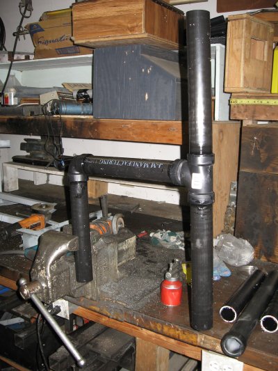
Glue the pieces to come up with this....
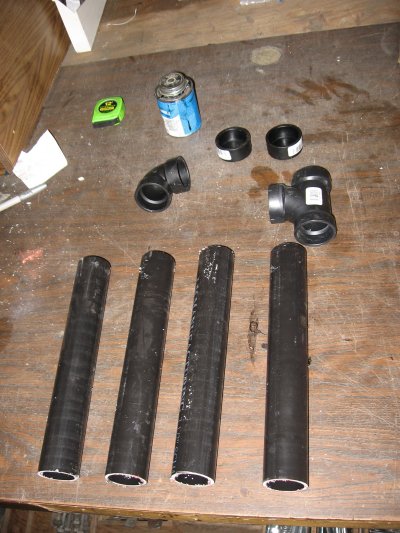
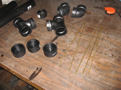
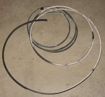
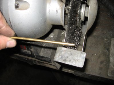
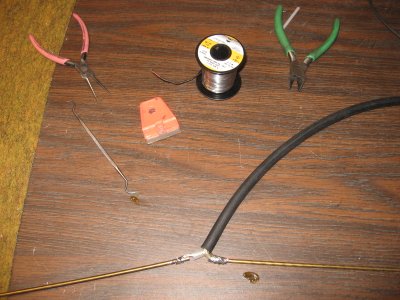
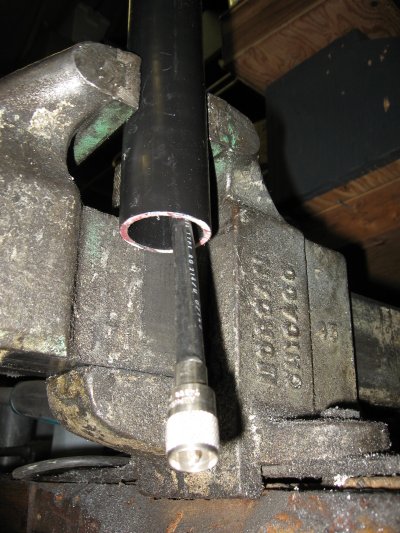
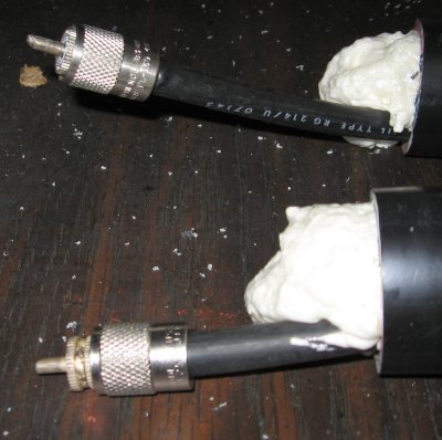
For the coax you'll need a bare minimum of 3 feet; that will allow a 4-5" "pigtail" out from the antenna. If you wish the "pigtail" longer, add that to this amount. Terminate one end of the coax with the connector you wish. For most sites the Author uses an "N" male connector for future installations and for current (but diminishing) replacements, a UHF male. Incidentally, most any coax will work, single or double braided. For best strength, stick with the larger size, such as the RG-8, RG-214 or RG-9 (being aware of possible PIM with the 9). Strip the other end back about 2" with the center and shield separated. Then cut two 12" pieces of the brass rod. Clean the ends off, then solder then to each of the coax conductors. Set that aside.
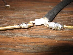
On the other end, cut back and solder each rod to the shield and center coax conductors. Set that aside to cool.
You need a way to get the coax and elements inside the protective (ABS) housing. With a weight and string put it into the low side of the dipole housing. You'll need to "work" it around the corners; with a little practice it will go much easier the second time around. Shake and rattle the weight around until you get it to come outside the coax entry point.
Tape the end of the string to the connector end of the coax. Pull it through until the dipole hot element is ready to fit inside. Now bend it back against the coax and continue pulling it inside the housing. Being careful, the joints will survive this maneuver. The Author's build a dozen or so over the years and never have broken the coax center, but be careful the first time.

Once the center feet point reaches the "Tee" it will fit properly into place at that point.
If you are concerned about the elements being straight up and down you can stuff a little foam against them and the inside housing surface.
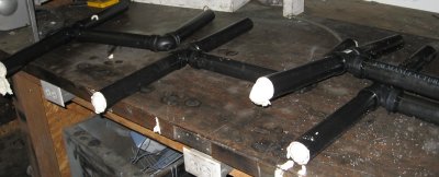
This is what the antenna should look like.
The last part is the easiest but messiest. Spray that expanding foam inside all three open ends to stabilize the elements from rattling, plus keep the bugs out of the coax exit point.
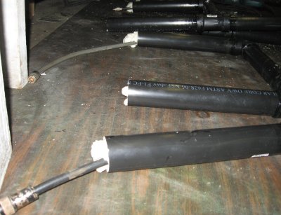
Once the foam is dry (next day), trim the top and bottom parts off , where the elements are. Then you can close the ends by gluing on the end caps. This will finish the antenna.
Hose clamps work great for mounting the antenna on a "V" type surface, such as "U" channel or "L" angle metal. See some of the other bracket projects for ideas like this. Last thing you might wish to test the return loss (VSWR) either hand held or mounted on the tower. The reason the pipe is all 12" is the wavelength, plus the distance from a side-mount tower arrangement will be 1/4 wave length for this band. If you wish other patterns adjust the one pipe's length between the Tee common and the 90* fitting.
![[SRG home Direction]](images/srghome.gif)